Description
P-AXIS-00092 | Position controller increments per revolution | |
Description | This parameter contains the number of position controller increments per revolution of the motor axis. The internal value used in the CNC kernel (value after assessing the value transmitted in the bus telegram) is output with the parameters P-AXIS-00405 (SERCOS and CANopen drives), or P-AXIS-00065 (PROFIDRIVE drives). When this parameter is used, the parameters P-AXIS-00362/P-AXIS-00363 and | |
Parameter | getriebe[i].incr_per_rev | |
Data type | UNS32 | |
Data range | 0 ≤ incr_per_rev ≤ MAX(UNS32) | |
Axis types | T, R, S | |
Dimension | T: Increments/ rev. | R,S: Increments/ rev. |
Default value | 1024 | |
Drive types | ---- | |
Remarks | For possible applications, see. Settings of position scaling | |
P-AXIS-00165 | Time offset of feed forward control setpoints | |
Description | This parameter defines a time offset in NC cycles between the output of the setpoints and the output of the calculated feedforward control values. With a value > 0, the feedforward control values are output before the associated setpoint. This parameter optimises the behaviour of the feedforward control axis. | |
Parameter | vorsteuer.shift_time | |
Data type | UNS16 | |
Data range | 0 ≤ shift_time ≤ 4 | |
Axis types | T, R, S | |
Dimension | T: Number of interpolation cycles | R,S: Number of interpolation cycles |
Default value | 3 | |
Drive types | Profidrive | |
Remarks |
| |
P-AXIS-00205 | Normalisation of the velocity (denominator) | |
Description | The conversion factor of the set velocity to drive format is obtained by specifying the value output to the drive and the related path distance covered in the time specified in P-AXIS-00207. This parameter specifies the conversion factor numerator. (P-AXIS-00206 is the numerator) This parameter indicates the path covered in the time specified in P-AXIS-00207, provided the value in P-AXIS-00206 is output to the drive. The path is specified in 1 µm or 0.001°. | |
Parameter | antr.v_reso_denom | |
Data type | UNS32 | |
Data range | 1 ≤ v_reso_denom ≤ MAX(UNS32) | |
Axis types | T, R, S | |
Dimension | T: 1µm | R,S: 0,001° |
Default value | 36 | |
Drive types | All drive types | |
Remarks |
| |
P-AXIS-00206 | Normalisation of command velocity (numerator) | |
Description | The conversion factor of the command velocity to drive format is defined by specifying the value output to the drive and the related distance covered in the time specified in P-AXIS-00207 . This parameter specifies the conversion factor numerator. (P-AXIS-00205 is the denominator) | |
Parameter | antr.v_reso_num | |
Data type | UNS32 | |
Data range | 0 ≤ v_reso_num ≤ MAX(UNS32) | |
Axis types | T, R, S | |
Dimension | T: increments | R,S: increments |
Default value | 1 | |
Drive types | All drive types | |
Remarks |
| |
P-AXIS-00207 | Time base for normalisation of velocity | |
Description | The time base for adapting the velocity interface to the unit used in the drive can be specified as value per minute, second or sampling interval. If normalisation per sampling interval is selected, the output value changes proportionally depending on the CNC cycle time at constant velocity. This may be essential depending on the drive. | |
Parameter | antr.v_time_base | |
Data type | UNS16 | |
Data range | 0: per minute 1: per second 2: per sampling interval | |
Axis types | T, R, S | |
Dimension | T: ---- | R,S: ---- |
Default value | 0 | |
Drive types | SERCOS | |
Remarks |
| |
P-AXIS-00223 | Feedforward control mode | |||
Description | This parameter specifies bit-coded which reference variables (velocity, acceleration and jerk) are to be active during feedforward control. | |||
Parameter | vorsteuer.vorsteuerung (feedforward) | |||
Data type | STRING | |||
Data range | Flag | Meaning | Value | |
NONE | No feedforward control | 0x0000 | ||
VEL | Velocity feedforward control | 0x0001 | ||
ACC | Acceleration feedforward control | 0x0002 | ||
JERK | Jerk feedforward control | 0x0004 | ||
ADD_VEL | Velocity feedforward control by output of an additive velocity command value () | 0x0101 | ||
ADD_ACC | Acceleration feedforward control by output of an additive torque/current command value | 0x0202 | ||
ADD_JERK | Jerk feedforward control by output of an additive torque/current command value | 0x0804 | ||
Axis types | T, R, S | |||
Dimension | T: ---- | R,S: ---- | ||
Default value | NONE | |||
Drive types | ---- | |||
Remarks | This function is available for all types of axes and types of drives. Jerk feedforward is only available when a jerk-limited velocity profile is used. For details on defining the acceleration profile, see P-CHAN-00071 and [PROG//Command #SLOPE [TYPE…] ].
The specification of values by codes is possible as of CNC Builds
.
Examples: Velocity and acceleration feedforward control: vorsteuer.vorsteuerung VEL | ACC
Velocity and acceleration feedforward control by additive command values: vorsteuer.vorsteuerung (feedforward) ADD_VEL | ADD_ACC
In previous CNC Builds values had to be specified bit-coded for the UNS16 variable. Default value: 0 | |||
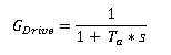
P-AXIS-00225 | Numerator equivalent time constant for feedforward control of acceleration | |
Description | The acceleration command variable is weighted by the mechanical time constant of the drive. The drive is modelled here as a first-order time delay element (see figure of the conventional feedforward control). The following transfer function in the Laplace range is obtained:
P-AXIS-00226: time constant denominator. | |
Parameter | vorsteuer.vs_a_faktor | |
Data type | SGN32 | |
Data range | 0 ≤ vs_a_faktor ≤ MAX(SGN32) | |
Axis types | T, R, S | |
Dimension | T: µs | R,S: µs |
Default value | 1 | |
Drive types | ---- | |
Remarks |
| |
 with
with 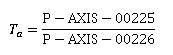
P-AXIS-00226 | Denominator equivalent time constant for feedforward control of acceleration | |
Description | The acceleration command variable is weighted by the mechanical time constant of the drive. The drive is modelled here as a first-order time delay element (see figure of the conventional feedforward control]). In the Laplace range the following transfer function is obtained
P-AXIS-00225: time constant numerator. | |
Parameter | vorsteuer.vs_a_nenner | |
Data type | SGN32 | |
Data range | 0 ≤ vs_a_nenner ≤ MAX(SGN32) | |
Axis types | T, R, S | |
Dimension | T: ---- | R,S: ---- |
Default value | 1 | |
Drive types | ---- | |
Remarks |
| |
P-AXIS-00228 | Numerator weighting factor for feedforward control | |
Description | This parameter describes the weighting factor for velocity and acceleration feedforward control.
| |
Parameter | vorsteuer.vs_v_faktor | |
Data type | SGN32 | |
Data range | 0 ≤ vs_v_faktor ≤ MAX(SGN32) | |
Axis types | T, R, S | |
Dimension | T: ---- | R,S: ---- |
Default value | 1 | |
Drive types | ---- | |
Remarks | We know from experience that the weighting factor should be in the range of 0.7 - 1. At values >1 the axis leads and impairs contour accuracy. | |
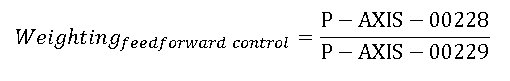
P-AXIS-00229 | Denominator weighting factor for feedforward control | |
Description | This parameter describes the weighting factor for velocity and acceleration feedforward control.
| |
Parameter | vorsteuer.vs_v_nenner | |
Data type | SGN32 | |
Data range | 0 ≤ vs_v_nenner ≤ MAX(SGN32) | |
Axis types | T, R, S | |
Dimension | T: ---- | R,S: ---- |
Default value | 1 | |
Drive types | ---- | |
Remarks | We know from experience that the weighting factor should be in the range of 0.7 - 1. At values >1 the axis leads and impairs contour accuracy. | |
P-AXIS-00255 | Permanent activation of feedforward control | |
Description | This parameter activates feedforward control permanently for one axis. Feedforward control is active all the time, even if G137 is active in the channel (or NC program). | |
Parameter | vorsteuer.default_active | |
Data type | BOOLEAN | |
Data range | 0/1 | |
Axis types | T, R, S | |
Dimension | T: ---- | R,S: ---- |
Default value | 0 | |
Drive types | ---- | |
Remarks | This function is available for all types of axes and types of drives. | |
P-AXIS-00325 | Numerator scaling factor for torque | |
Description | Numerator of the scaling factor for the commanded torque to the drive. The factor is specified as a quotient. This quotient is the value which must be output to the motor to reach the nominal torque. | |
Parameter | antr.torque_scale_num | |
Data type | UNS32 | |
Data range | 0 < torque_scale_num < MAX(UNS32) | |
Axis types | T, R, S | |
Dimension | T: ---- | R,S: ---- |
Default value | 1 | |
Drive types | SERCOS, Lightbus,CANopen | |
Remarks |
| |
P-AXIS-00326 | Denominator scaling factor for torque | |
Description | Denominator of the scaling factor for the commanded torque to the drive. The factor is specified as a quotient. This quotient is the value which must be output to the motor to reach the nominal torque. | |
Parameter | antr.torque_scale_denom | |
Data type | UNS32 | |
Data range | 1 < torque_scale_denom < MAX(UNS32) | |
Axis types | T, R, S | |
Dimension | T: ---- | R,S: ---- |
Default value | 1 | |
Drive types | SERCOS, Lightbus,CANopen | |
Remarks | If the value 0 is set for P-AXIS-00326, an error message with the ID number P-ERR-110465 is output and the internal scaling factor is set to 0 In this case no output of the additive torque command value to the drive is sent. | |
P-AXIS-00337 | Numerator of scaling factor for jerk feedforward | |
Description | This parameter specifies the numerator of the scaling factor for jerk feedforward control. The scaling factor for jerk feedforward control is defined as: jerk_fact = P-AXIS-00337/P-AXIS-00338 The output of the jerk feedforward control command value to the drive must be activated by setting bit 0x04 in axis parameter P-AXIS-00223 . | |
Parameter | vorsteuer.jerk_fact_num | |
Data type | UNS32 | |
Data range | 0 ≤ jerk_fact_num ≤ MAX(UNS32) | |
Axis types | T, R, S | |
Dimension | T: ---- | R,S: ---- |
Default value | 1 | |
Drive types | ---- | |
Remarks | Jerk feedforward control is only possible if a jerk-limited acceleration profile is used. For non jerk-limited acceleration profiles a jerk command value of 0 is output. For details on defining the acceleration profile, see P-CHAN-00071 and [PROG//Command #SLOPE [TYPE…] ]. | |
P-AXIS-00338 | Denominator of scaling factor for jerk feedforward | |
Description | This parameter specifies the denominator of the scaling factor for jerk feedforward control. The scaling factor for jerk feedforward control is defined as: jerk_fact = P-AXIS-00337/ P-AXIS-00338 The output of the jerk feedforward control command value to the drive must be activated by setting bit 0x04 in axis parameter P-AXIS-00223 . | |
Parameter | vorsteuer.jerk_fact_denom | |
Data type | UNS32 | |
Data range | 0 < jerk_fact_denom ≤ MAX(UNS32) | |
Axis types | T, R, S | |
Dimension | T: ---- | R,S: ---- |
Default value | 100 | |
Drive types | ---- | |
Remarks | Jerk feedforward control is only possible if a jerk-limited acceleration profile is used. For non jerk limited acceleration profiles a jerk command value of 0 is output. For details on defining the acceleration profile, see P-CHAN-00071 and [PROG//Command #SLOPE [TYPE…] ]. A value of 0 is inadmissible for this parameter. If this value is specified nevertheless, an error message with error code 110473 is output and the value is corrected to the default (100). | |
P-AXIS-00362 | Encoder resolution via feed constant (numerator) | |
Description | Parameter P-AXIS-00362 and parameter P-AXIS-00363 enable anm alternative method to parameterise encoder resolution. If either parameter P-AXIS-00362 or P-AXIS-00363 are assigned values unequal to 1 (default initialisation), encoder resolution is calculated based on the equation below:
where: R: Resulting resolution (Increments / 0.1µm) rMotor: Encoder increments per motor revolution (P-AXIS-00092) iGetriebe; Gear transmission ratio (Revolutions gear input / Revolutions gear output (P-AXIS-00511/P-AXIS-00512)). f: Feed constant (0.1µm / Revolution) (P-AXIS-00362/P-AXIS-00363).
| |
Parameter | antr.feed_const_num | |
Data type | UNS32 | |
Data range | 1 ≤ feed_const_num ≤ MAX(UNS32) | |
Axis types | T, R, S | |
Dimension | T: 0.1 µm | R,S: 0.1 µm |
Default value | 1 | |
Drive types | --- | |
Remarks | If P-AXIS-00362/ P-AXIS-000363 are used, the parameters P-AXIS-00233 and P-AXIS-00234 must be set to 1. For possible applications, see Settings of position scaling | |
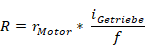
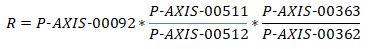
P-AXIS-00363 | Encoder resolution via feed constant (denominator) | |
Description | Parameter P-AXIS-00362 and parameter P-AXIS-00363 enable an alternative method to parametrise encoder resolution. If either parameter P-AXIS-00362 or P-AXIS-00363 are assigned values unequal to 1 (default initialisation), encoder resolution is calculated based on the equation below:
where: R: Resulting resolution (Increments / 0.1µm) rMotor: Encoder increments per motor revolution (P-AXIS-00092) iGetriebe: Gear transmission ratio (Revolutions gear input / Revolutions gear output (P-AXIS-00511/P-AXIS-00512)). f: Feed constant (0.1µm / Revolution) (P-AXIS-00362/ P-AXIS-00363).
| |
Parameter | antr.feed_const_denom | |
Data type | UNS32 | |
Data range | 1 ≤ feed_const_denom ≤ MAX(UNS32) | |
Axis types | T, R, S | |
Dimension | T: U | R,S: U |
Default value | 1 | |
Drive types | --- | |
Remarks | If P-AXIS-00362 / P-AXIS-000363 are used, the parameters P-AXIS-00233 and P-AXIS-00234 must be set to 1. For possible applications, see Settings of position scaling | |
P-AXIS-00389 | Delay time for velocity feedforward | |
Description | If velocity feedforward control via an additive velocity command value is activated, this parameter can delay the output of the velocity feedforward control value with respect to the command position. The delay time unit is in µs. Maximum delay is six interpolator cycles. | |
Parameter | vorsteuer.velocity_delay_time | |
Data type | UNS16 | |
Data range | 0 ≤ velocity_delay_time < 6*interpolator cycle time | |
Axis types | T, R, S | |
Dimension | T: µs | R,S: µs |
Default value | 0 | |
Drive types | SERCOS, Profidrive, CANopen | |
Remarks | If the permitted value of P-AXIS-00389 is exceeded, the error message P-ERR-70349 is output and P-AXIS-00389 is corrected to 0. | |
P-AXIS-00390 | Delay time for acceleration feedforward | |
Description | If acceleration feedforward control via an additive torque command value is activated, this parameter delays the output of the acceleration feedforward control value with respect to the command position. The delay time unit is in µs. Maximum delay is six interpolator cycles. | |
Parameter | vorsteuer.acceleration_delay_time | |
Data type | UNS16 | |
Data range | 0 < acceleration_delay_time < 6*Interpolator cycle time | |
Axis types | T, R, S | |
Dimension | T: µs | R,S: µs |
Default value | 0 | |
Drive types | SERCOS, Lightbus, Profidrive, CANopen | |
Remarks | If the permitted value of P-AXIS-00390 is exceeded, the error message P-ERR-70348 is output and P-AXIS-00390 is corrected to 0. | |
P-AXIS-00391 | Load inertia | |
Description | To set up acceleration feedforward with additive torque command value, the total load inertia of the motor must be configured here. The total load inertia is the inertia of the motor itself and the inertia of the load related to the motor shaft. In case of a translatory moved axis, the moved masses must be converted to an equivalent inertia related to the motor shaft. | |
Parameter | getriebe[i].load | |
Data type | REAL64 | |
Data range | 0 ≤ load < MAX(REAL64) | |
Axis types | T, R, S | |
Dimension | T: kg | R,S: kg*m² |
Default value | 1.000000e-006 | |
Drive types | SERCOS | |
Remarks |
| |
P-AXIS-00392 | Reference value for converting torque values to the motor format. | |
Description | This parameter is used for the scaling of the additive torque command if acceleration feedforward control is used with additive command values. The motor stall torque must be enetered. | |
Parameter | antr.acc_reference_value | |
Data type | REAL64 | |
Data range | 0 ≤ acc_reference_value < MAX(REAL64) | |
Axis types | T, R, S | |
Dimension | T: N | R,S: Nm |
Default value | 1 | |
Drive types | SERCOS, CANopen | |
Remarks |
| |
P-AXIS-00511 | Gearbox ratio numerator | |
Description | By default, the path resolution of an axis is set with axis parameters P-AXIS-00233 and P-AXIS-00234 , where an eventually present gearbox must be considered (load-side scaling). If the parameters P-AXIS-00511/ P-AXIS-00512 and P-AXIS-00092, P-AXIS-00362/ P-AXIS-00363 are used, the resolution of the axis can be specified related to the motor side. The resulting resolution (R) related to the load side is calculated automatically according to the equation below:
| |
Parameter | getriebe[i].gear_fact_num | |
Data type | UNS32 | |
Data range | 1 ... MAX (UNS32) | |
Axis types | T, R, S | |
Dimension | T: ---- | R,S: ---- |
Default value | 1 | |
Drive types | ---- | |
Remarks | For possible applications, see Settings of position scaling | |
P-AXIS-00512 | Gearbox ratio denominator | |
Description | By default, the path resolution of an axis is specified with axis parameters P-AXIS-00233 and P-AXIS-00234 , where an eventually present gearbox must be considered (load-side scaling). If the parameters P-AXIS-00511/ P-AXIS-00512 and P-AXIS-00092, P-AXIS-00362/ P-AXIS-00363 are used, the resolution of the axis can be specified related to the motor side. The resulting resolution (R) related to the load side is calculated automatically according to the equation below:
| |
Parameter | getriebe[i].gear_fact_denom | |
Data type | UNS32 | |
Data range | 1 ... MAX (UNS32) | |
Axis types | T, R, S | |
Dimension | T: ---- | R,S: ---- |
Default value | 1 | |
Drive types | ---- | |
Remarks | A value of zero is not permitted for P-AXIS-00512. If this value is set, the error message P-ERR-110579 is output. For possible applications, see Settings of position scaling | |