Tool radius compensation (TRC)
Tool radius compensation (TRC) allows programming of the workpiece contour independently of tool geometry. If TRC is selected (G41, G42), a tool path equidistant from this programmed tool contour is calculated at distance "tool radius".
Tool radius compensation acts in the plane selected with G17, G18 or G19. The tool compensation values used are the tool compensation synchronisation modes stored under the D words (see Tool geometry compensation).
Tool radius can also be changed when TRC is active by selecting a new D word or writing the variable V.G.WZ_AKT.R.
When a negative tool radius is used, the selection side of the TRC is changed automatically.

Overview of all TRC-relevant G functions:
Selecting/deselecting TRC
G40 | Deselecting TRC | (modal, initial state) |
G41 | Selecting TRC left of contour | (modal) |
G42 | Selecting TRC right of contour | (modal) |
Selecting/deselecting TRC
Direct TRC selection/deselection | (modal) | |
Indirect TRC selection/deselection | (modal, initial state) | |
Direct TRC selection/deselection on the path | (modal) | |
Perpendicular TRC selection/deselection | (modal) | |
Selecting inside corner of TRC | (modal) | |
Selecting/deselecting TRC directly without block | (modal) | |
Tangential TRC selection/deselection | (non-modal) |
Attention

It is not permitted to change the modal selection method to G238 when TRC is selected.
Feed adaption:
Constant feedrate | (modal, initial state) | |
Adapted feedrate | (modal) |
Contour masking:
Deselecting contour masking | (modal, initial state) | |
Selecting contour masking | (modal) |
Selecting external transitions:
Outside corners must be bypassed if tool radius compensation is selected. For this purpose, tool radius compensation inserts transition blocks. Use G25 and G26 to select between linear block insertion and circular block insertion.
G25 | Linear transition | (modal, initial state) |
G26 | Circular transition | (modal) |
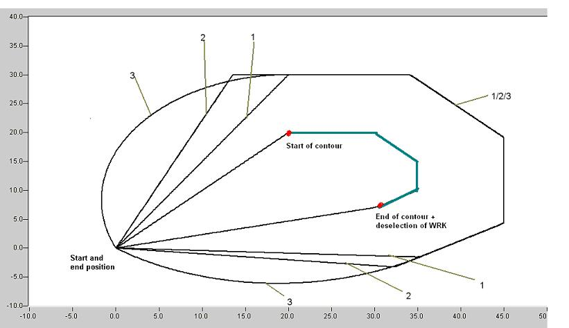
Programing Example

Presentation of the different selection options when tool radius compensation is used. This shows the commands for direct, indirect and tangential selection/deselection of TRC (G139/G138/G05) in combination with the TRC transition types for linear and circular transition (G25/G26).
The test programs are executed with a tool radius of 10 mm.
Example 1 | G138 | G139 | G05 |
G25 | Path 1 | Path 2 | Path 3 |
%WZKG25 (Contour for G25)
N1 G00 G90 T1 D1 X0 Y0 Z0 G17
(Display of contour)
N15 G01 X20 Y20 F1000
N20 G91
N25 G1 X10
N30 X5 Y-5
N35 Y-5
N40 X-5 Y-3
N45 G01 G90 X0 Y0 F1000
(Path 1)
N100 G138 G41 (Select directly and TRC left of contour)
N105 G01 X20 Y20 F1000 (Required compensation motion after G41)
N110 G25 (G25 linear transitions)
N115 G1 G91 X10
N120 X5 Y-5
N125 Y-5
N130 X-5 Y-3
N135 G138 G40 (Deselect directly and deselect TRC)
N140 G01 G90 X0 Y0 F1000 (Required compensation motion after G40)
(Path 2)
N200 G139 G41 (Select directly and TRC left of contour)
N205 G01 X20 Y20 F1000 (Required compensation motion after G41)
N210 G25 (G25 linear transitions)
N215 G1 G91 X10
N220 X5 Y-5
N225 Y-5
N230 X-5 Y-3
N235 G139 G40 (Deselect indirectly and deselect TRC)
N240 G01 G90 X0 Y0 F1000 (Required compensation motion after G40)
(Path 3)
N300 G05 G41 (Tangential selection and TRC left of contour)
N305 G01 X20 Y20 F1000 (Required compensation motion after G41)
N310 G25 (G25 linear transitions)
N315 G1 G91X10
N320X5 Y-5
N325 Y-5
N330 X-5 Y-3
N335 G05 G40 (Tangential deselection and deselect TRC)
N340 G01 X20 Y20 F1000 (Required compensation motion after G41)
N999 M30
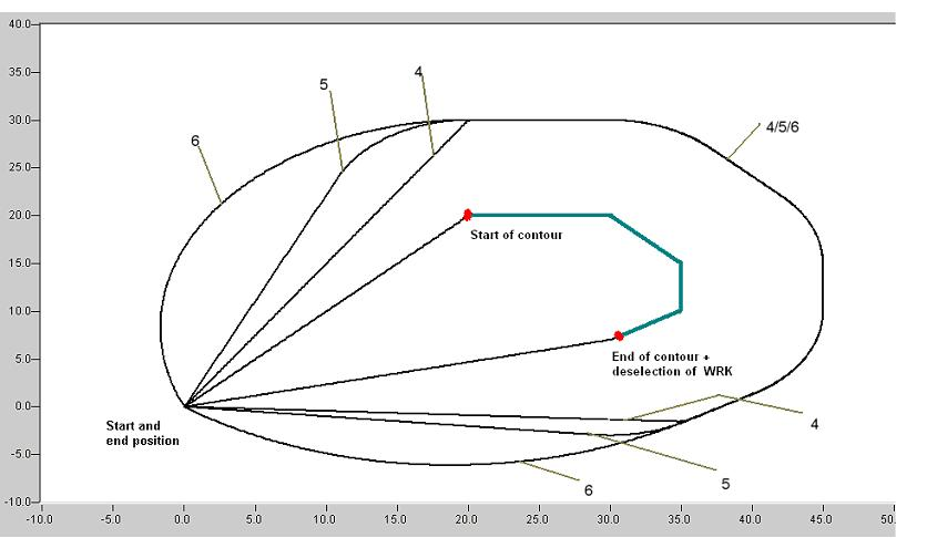
Example 2 | G138 | G139 | G05 |
G26 | Path 4 | Path 5 | Path 6 |
%WZKG26 (Contour for G26)
N10 G00 G90 T1 D1 X0 Y0 Z0 G17
(Display of contour)
N15 G01 X20 Y20 F1000
N20 G91
N25 G1 X10
N30 X5 Y-5
N35 Y-5
N40 X-5 Y-3
N45 G01 G90 X0 Y0 F1000
(Path 4)
N400 G138 G41 (Select directly and TRC left of contour)
N405 G01 X20 Y20 F1000 (Required compensation motion after G41)
N410 G26 (G26 Circular transitions)
N415 G1 G91 X10
N420 X5 Y-5
N425 Y-5
N430 X-5 Y-3
N435 G138 G40 (Deselect directly and deselect TRC)
N440 G01 G90 X0 Y0 F1000 (Required compensation motion after G40)
(Path 5)
N500 G139 G41 (Select directly and TRC left of contour)
N505 G01 X20 Y20 F1000 (Required compensation motion after G41)
N510 G26 (G26 Circular transitions)
N515 G1 G91 X10
N520 X5 Y-5
N525 Y-5
N530 X-5 Y-3
N535 G139 G40 (Deselect indirectly and deselect TRC)
N540 G01 G90 X0 Y0 F1000 (Required compensation motion after G40)
(Path 6)
N600 G05 G41 (Tangential selection and TRC left of contour)
N605 G01 X20 Y20 F1000 (Required compensation motion after G41)
N610 G26 (G26 Circular transitions)
N615 G1 G91X10
N620 X5 Y-5
N625 Y-5
N630 X-5 Y-3
N635 G05 G40 (Tangential deselection and deselect TRC)
N640 G01 X20 Y20 F1000 (Required compensation motion after G41)
N999 M30
Change tool data
Programing Example
Change tool data
:
N30 G0 D0 X0 Y0 Z0 G17 (X-Y plane)
N40 G0 D100 X10 Y10 (Select TLC)
N50 G1 Z0
N60 G0 Z100
N70 G41 (Select TRC with data block D100)
N80 G1 Z0
N90 G2 X10 Y10 I-15 (Full circle with radius 15)
N100 G0 Z100
N110 D2 Z200 (Other compensation data block, i.e.)
(other values for TLC and TRC)
N120 G1 Z0 (Compensating motion)
(motion of TLC takes place here)
N130 G1 X20 Y20 (Compensating motion of TRC)
N140 G02 X10 Y10 I-15 (TRC is now executed with data)
(block D2)
N150 G0 Z100
N160 G40 (Deselect TRC)
N170 X0
:
Dynamic change of tool radius:
Another option to change tool radius is to assign variables (see also Chap. 13). For example, this takes into consideration the wear and tear of grinding tools during motion blocks.
Programing Example
Dynamic change of tool radius:
N00 G1 G90 X0 D6 F5
N10 G41 G26 (Select TRC)
N20 X0 Y250 (Starting point)
N30 V.P.VERSCHLEISS = 0.010
N100 $FOR V.P.LAUF = 0,100,10 (Grinding cycle)
N110 X300
N120 Y200
N130 X0
N140 Y250 (Tool radius gradually becomes smaller)
N150 V.G.WZ_AKT.R = V.G.WZ_AKT.R – V.P.VERSCHLEISS
N160 $ENDFOR
N200 G40 X300 (Deselect TRC)
N999 M30
Additional information
- Direct/indirect deselection of TRC
- Direct/indirect deselection of TRC
- Perpendicular selection/deselection of TRC (G237)
- Selecting inside corner of TRC (G238)
- Direct selection/deselection of TRC without block (G239)
- Direct selection/deselection of TRC on the path (G236)
- Generate compensation blocks
- Reaction on contour change
- Reaction to change in tool radius
- Tangential selection/deselection of TRC (G05)
- Adapting feed of TRC (G10/G11)
- Selecting/deselecting TRC contour masking (G140/G141)
- Limits of TRC
- Programmable additional options of TRC (#TRC)
- Exception list of commands with active TRC/SRK