Axis control commands
Feed rate enable, axis | |
Description | Axis-specific feed rate enable The feed rate enable must be set for all axes to be moved. If this is not the case, no path motion occurs. |
Data type | MC_CONTROL_BOOL_UNIT, see description of Control unit |
Special features | SERCOS drives With SERCOS drives, the datum is derived from bit 13 of the control word. |
Access | PLC reads request_r + state_r and writes command_w + enable_w |
ST path | gpAx[axis_idx]^.lr_mc_control.release_feedhold |
Commanded, requested and return values | |
ST element | .command_w .request_r |
Data type | BOOL |
Value range | [TRUE = drive enable, transition TRUE → FALSE: The drive is shut down in compliance with the acceleration parameters. FALSE = Drive STOP] |
Return value | |
ST element | .state_r |
Data type | BOOL |
Value range | [TRUE = drive enable, FALSE = drive STOP] |
Redirection | |
ST element | |
Feedhold ON/OFF, axis | |
Description | Axis-specific feedhold The axis-specific feedhold on an axis acts as follows:
Otherwise, the global feedhold of the channel acts on al axes except for spindles. The operation mode of the global and axis-specific feedhold can be parameterised for these axes (P-AXIS-00529, P-AXIS-00540). |
Data type | MC_CONTROL_BOOL_UNIT, see description of Control unit |
Access | PLC reads request_r + state_r and writes command_w + enable_w |
ST path | gpAx[axis_idx]^.ipo_mc_control.feedhold |
Commanded, requested and return values | |
ST element | .command_w .request_r .state_r |
Data type | BOOL |
Value range | [TRUE = feedhold on, FALSE = feedhold off] |
Redirection | |
ST element | |
Directional feedhold, axis | |||
Description | Axis-specific directional feedhold A directional feedhold can be set for all moving axes If an axis command is in the block direction, the axis-specific feedhold is set. An axis-specific directional feedhold acts on an axis in exactly the same way as an axis-specific feedhold.
The directional and normal axis-specific feedholds can be superimposed. Otherwise, the global feedhold of the channel acts on al axes except for spindles. The operation mode of the global and axis-specific feedhold can be parameterised for these axes (P-AXIS-00529, P-AXIS-00540). | ||
Data type | MC_CONTROL_UNS08_UNIT, see description of Control unit | ||
Access | PLC reads request_r + state_r and writes command_w + enable_w | ||
ST path | gpAx[axis_idx]^.ipo_mc_control.directional_feedhold | ||
Commanded, requested and return values | |||
ST element | .command_w .request_r .state_r | ||
Data type | USINT | ||
Value range | Value | PLC constant | Meaning |
0 | HLI_DIRECTIONAL_FEEDHOLD_NO_FEEDHOLD | The axis is not blocked in any motion direction. | |
1 | HLI_DIRECTIONAL_FEEDHOLD_POS | The axis is blocked in the positive motion direction. | |
2 | HLI_DIRECTIONAL_FEEDHOLD_NEG | The axis is blocked in the negative motion direction. | |
3 | HLI_DIRECTIONAL_FEEDHOLD_POS_NEG | The axis is blocked in the positive and negative motion directions. | |
Redirection | |||
ST element | |||
Special feature | The axis drive is shut down in compliance with the acceleration parameters. This means that the axis moves a short distance in the blocked direction before stopping. The feedhold always acts on the complete current block, This means that a block can be blocked even if the current direction of axis motion is not pointing in the blocked direction. Available as of V3.1.3079.26 Examples: 1. Example of a circle: 2. Example of polynomial contouring: 3. Special case of a spindle: | ||
Feedhold watchdog | |
Description | This control unit is the interface of a watchdog which stops the CNC interpolator by activating a feedhold if the PLC fails. If the axis for which the watchdog was triggered is a member of an axis group and is currently commanded to be in motion, all other axes moved by this command also stop. If this control unit is enabled, the PLC must set the element command_w to TRUE in every PLC cycle. The NC kernel than resets the command back to FALSE. To enable this control unit function, the axis parameter enable_feed_enable (P-AXIS-00313) must be set in many versions of the NC kernel. In other version the function of this control unit is still available. |
Data type | MC_CONTROL_BOOL_UNIT, see description of Control unit |
Access | PLC reads request_r + state_r and writes command_w + enable_w |
ST path | gpAx[axis_idx]^.ipo_mc_control.enable_feed_wdg |
Commanded, requested and return values | |
ST element | .command_w .request_r .state_r |
Data type | BOOL |
Value range | [TRUE = signals that PLC is invoked cyclically and executes its function, FALSE] |
Redirection | |
ST element | |
Feed override, axis | |
Description | Axis-specific feed override The axis-specific feed override permits weighting the axis path velocity with an additional factor. The axis-specific feed override only acts on an axis if the axis is currently moved in manual mode or as an independent axis and but in a path compound. Otherwise the global override of the channel acts on the axis. The axis-specific feed override also acts on single axes and spindles. With spindles the feed override also acts on the velocity acknowledgement of programmed M3/ M4 or MC_MoveVelocity commands. Velocity acknowledgement occurs when the weighted feed rate is reached and in extreme cases when the feed rate is 0. (see lr_state.rev_erreicht_r) |
Data type | MC_CONTROL_UNS16_UNIT, see description of Control unit |
Access | PLC reads request_r + state_r and writes command_w + enable_w |
ST path | gpAx[axis_idx]^.ipo_mc_control.override |
Commanded, requested and return values | |
ST element | .command_w .request_r .state_r |
Data type | UINT |
Unit | 0.1% |
Value range | [0, P-AXIS-00109] The parameter P-AXIS-00109 is an axis-specific parameter. The value is typically 1000. |
Redirection | |
ST element | |
Feed override valid, axis | |
Description | Axis-specific feed override valid. |
Data type | MC_CONTROL_BOOL_UNIT, see description of Control unit |
Access | PLC reads request_r + state_r and writes command_w + enable_w |
ST path | gpAx[axis_idx]^.ipo_mc_control.override_valid |
Commanded, requested and return values | |
ST element | .command_w .request_r .state_r |
Data type | BOOL |
Value range | [TRUE = axis-specific feed override valid, FALSE] |
Redirection | |
ST element | |
Drive ON | |
Description | Drive ON |
Data type | MC_CONTROL_BOOL_UNIT, see description of Control unit |
Special features | SERCOS drives With SERCOS drives, the datum is derived from bit 15 of the control word. |
Access | PLC reads request_r + state_r and writes command_w + enable_w |
ST path | gpAx[axis_idx]^.lr_mc_control.drive_on |
Commanded and requested values | |
ST element | .command_w .request_r |
Data type | BOOL |
Value range | [TRUE = drive ON, transition TRUE → FALSE: The drive is shut down in the best possible manner. FALSE = Drive OFF] |
Return value | |
ST element | .state_r |
Data type | BOOL |
Value range | [TRUE = drive ON, FALSE = drive OFF] |
Redirection | |
ST element | |
Controller enable | |
Description | Control unit enable ↔ axis-specific torque connection. |
Data type | MC_CONTROL_BOOL_UNIT, see description of Control unit |
Special features | SERCOS drives With SERCOS drives, the datum is derived from bit 14 of the control word. |
Access | PLC reads request_r + state_r and writes command_w + enable_w |
ST path | gpAx[axis_idx]^.lr_mc_control.torque_permission |
Commanded, requested and return values | |
ST element | .command_w .request_r .state_r |
Data type | BOOL |
Value range | [TRUE = torque connection, FALSE = drive is torque-free] |
Redirection | |
ST element | |
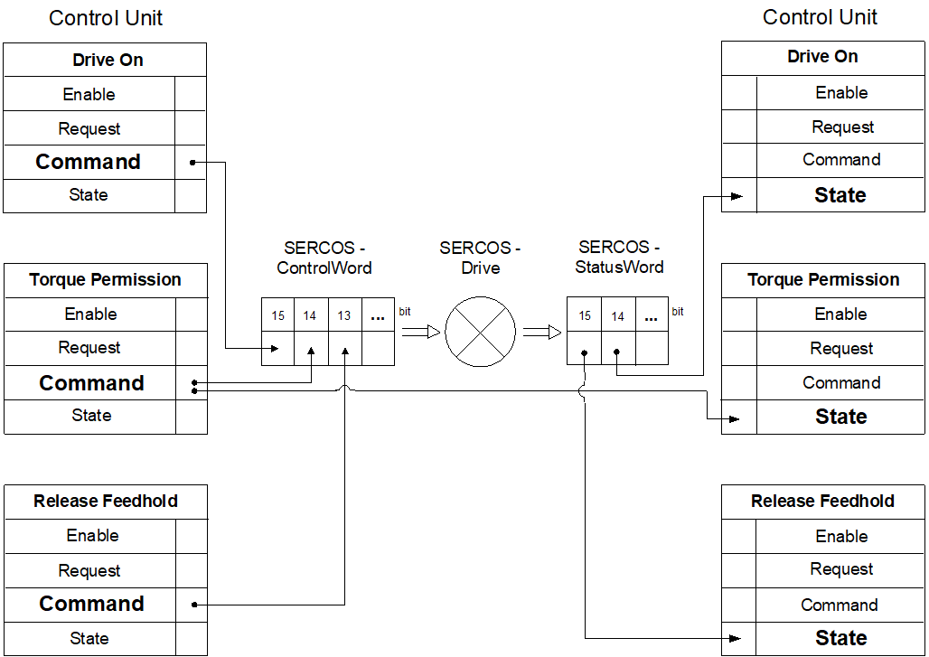
The diagram below shows the relationship between HLI control units and the SERCOS control word or the SERCOS status word for SERCOS drives.
Reference cam | |
Description | Reference cam signal when homing. |
Data type | MC_CONTROL_BOOL_UNIT, see description of Control unit |
Special features | When this signal is commanded, it only acts if the parameter lr_hw[i].cam_direct_access = 0 (P-AXIS-00036) is set in the axis machine data record of the associated axis. When the characteristic value lr_hw[i].cam_level (Description) is used in the axis machine data record, the action of this command can be set from high-active to low-active. The default action is described below. |
Access | PLC reads request_r + state_r and writes command_w + enable_w |
ST path | gpAx[axis_idx]^.lr_mc_control.reference_cam |
Commanded, requested and return values | |
ST element | .command_w .request_r .state_r |
Data type | BOOL |
Value range | [TRUE = reference cam switched, FALSE = reference cam not switched] |
Redirection | |
ST element | |
Reduced velocity, axis | |
Description | When this signal is set, the axis velocity in G00 and G01 is reduced to the values defined in the axis parameters P-AXIS-00214 or P-AXIS-00155. |
Data type | MC_CONTROL_BOOL_UNIT, see description of Control unit |
Special features | If this axis is in a channel, the limits of the other axes participating in the motion are also considered. The effective value for reduced velocity is determined so that none of the axes participating in the motion overshoots its configured limit. The response is then identical to the command via a channel. |
Access | PLC reads request_r + state_r and writes command_w + enable_w |
ST path | gpAx[axis_idx]^.ipo_mc_control.reduced_speed |
Commanded, requested and return values | |
ST element | .command_w .request_r .state_r |
Data type | BOOL |
Value range | [TRUE = reduced velocity active, FALSE = reduced velocity not active] |
Redirection | |
ST element | |
Reduced velocity in zone 1, axis | |
Description | By setting this signal, the axis velocity is limited to the velocity defined in the axis parameter P-AXIS-00030 when the axis is located within the range defined by the parameters P-AXIS-00085 and P-AXIS-00093. If necessary the axis is decelerated after entering the zone. |
Data type | MC_CONTROL_BOOL_UNIT, see description of Control unit |
Special features | If the axis is in a channel, the limits of the other axes participating in the motion and also located within their configured zone are considered. |
Access | PLC reads request_r + state_r and writes command_w + enable_w |
ST path | gpAX[axis_idx]^.ipo_mc_control.reduced_speed_zone |
Commanded, requested and return values | |
ST element | .command_w .request_r .state_r |
Data type | BOOL |
Value range | [TRUE = reduced velocity in zone 1 active, FALSE = reduced velocity in zone 1 not active] |
Redirection | |
ST element | |
Reduced velocity in zone 2, axis | |
Description | By setting this signal, the axis velocity is limited to the velocity defined in the axis parameter P-AXIS-00030 when the axis is located within the range defined by the parameters P-AXIS-00097 and P-AXIS-00105. If necessary the axis is decelerated after entering the zone. |
Data type | MC_CONTROL_BOOL_UNIT, see description of Control unit |
Special features | If the axis is in a channel, the limits of the other axes participating in the motion and also located within their configured zone are considered. |
Access | PLC reads request_r + state_r and writes command_w + enable_w |
ST path | gpAX[axis_idx]^.ipo_mc_control.reduced_speed_2_zone |
Commanded, requested and return values | |
ST element | .command_w .request_r .state_r |
Data type | BOOL |
Value range | [TRUE = reduced velocity in zone 2 active, FALSE = reduced velocity in zone 2 not active] |
Redirection | |
ST element | |
Suppress read-in enable | |
Description | Suppress read-in enable When the read-in enable (setting NoEfg) is cleared, the interpolator does not read any new previously decoded NC motion information, i.e. the motion is stopped at the end of the current commands in the interpolator. |
Data type | MC_CONTROL_BOOL_UNIT, see description of Control unit |
Access | PLC reads request_r + state_r and writes command_w + enable_w |
ST path | gpAx[axis_idx]^.ipo_mc_control.no_efg |
Commanded, requested and return values | |
ST element | .command_w .request_r .state_r |
Data type | BOOL |
Value range | [TRUE = no read-in enable, FALSE = read-in enable] |
Redirection | |
ST element | |
Machining simulation, axis | |
Description | Activates and deactivates an axis-specific machining simulation. During machining simulation, all axis-specific technology commands of the NC program are no longer output to the PLC but are acknowledged internally. |
Data type | MC_CONTROL_BOOL_UNIT, see description of Control unit |
Access | PLC reads request_r + state_r and writes command_w + enable_w |
ST path | gpAx[axis_idx]^.ipo_mc_control.machining_simulation |
Commanded, requested and return values | |
ST element | .command_w .request_r .state_r |
Data type | BOOL |
Value range | [TRUE = machining simulation active, FALSE = machining simulation inactive] |
Redirection | |
ST element | |
Ignore minimum tool velocity | |
Description | If a value for minimum tool velocity is configured at tool change, the NC kernel monitors that this limit is not undershot by specifying an override. This control unit can switch this response off and the override acts on the axis as specified. |
Data type | MC_CONTROL_BOOL_UNIT, see description of Control unit |
Special features | Control unit is only effective if the axis is a spindle. |
Access | PLC reads request_r + state_r and writes command_w + enable_w |
ST path | gpAx[axis_idx]^.ipo_mc_control.ignore_vb_min_tool |
Commanded, requested and return values | |
ST element | .command_w .request_r .state_r |
Data type | BOOL |
Value range | [TRUE = undershooting minimum tool velocity permitted, FALSE] |
Redirection | |
ST element | |
OTC offset | |
Description | When this wear offset is set, wear in the direction of this axis can be compensated. When the SURF_NORM_ORI mode is used (wear in the direction of the surface normal), the offset value must be assigned in the third axis. |
Data type | MC_CONTROL_SGN32_UNIT, see description of Control unit |
Special features | The wear offset is distributed by the CNC over several cycles. |
Access | PLC reads request_r + state_r and writes command_w + enable_w |
ST path | gpAx[axis_idx]^.ipo_mc_control.otc_offset |
Commanded, requested and return values | |
ST element | .command_w .request_r .state_r |
Data type | DINT |
Unit | 0.1 µm |
Value range | |
Redirection | |
ST element | |
Move back manual mode offset | |
Description | If manual mode is active in the channel and if the commanded axis fails to move, the axis is moved by this command so that afterwards manual mode offset is 0. |
Data type | MC_CONTROL_BOOL_UNIT, see description of Control unit |
Special features | A rising edge (FALSE → TRUE) at command_w initiates the process. The signal is ignored if a manual mode motion is still active or manual mode offset is already 0. |
Access | PLC reads request_r + state_r and writes command_w + enable_w |
ST path | gpAx[axis_idx]^.ipo_mc_control.manual_mv_back_to_start |
Commanded, requested and return values | |
ST element | .command_w .request_r .state_r |
Data type | BOOL |
Value range | rising edge (FALSE → TRUE) triggers backward motion |
Redirection | |
ST element | |
Stop the motion “Move back manual mode offset” | |
Description | The motion that was started by the control unit command “Move back manual mode offset” is stopped by the control unit with this command. |
Data type | MC_CONTROL_BOOL_UNIT, see description of Control unit |
Special features | A rising edge (FALSE → TRUE) initiates the command. Up to final axis standstill, the data item Axis-specific interpolator, state shows that the stop process is active with the HLI_AX_MAN_MV_BACK_WAIT_STOP bit. |
Access | PLC reads request_r + state_r and writes command_w + enable_w |
ST path | gpAx[axis_idx]^.ipo_mc_control.manual_mv_back_stop |
Commanded, requested and return values | |
ST element | .command_w .request_r .state_r |
Data type | BOOL |
Value range | [TRUE = rising edge stops the motion, FALSE] |
Redirection | |
ST element | |
Tracking mode | |
Description | The axis is set to tracking mode, i.e. the command value is set identical to the actual value read in. Setting the command and actual values equal is executed and command_w = TRUE. |
Data type | MC_CONTROL_BOOL_UNIT, see description of Control unit |
Special features | By setting the command and actual value equal, the current position lag is = 0. This may result in an external force (weight of the axis) slowly changing the axis position (drift). |
Access | PLC reads request_r + state_r and writes command_w + enable_w |
ST path | gpAx[axis_idx]^.lr_mc_control.follow_up |
Commanded, requested and return values | |
ST element | .command_w .request_r .state_r |
Data type | BOOL |
Value range | [TRUE = control loop open, FALSE] |
Redirection | |
ST element | |
Run out gantry difference | |
Description | If the axis is a gantry slave axis and both the master and slave are referenced, the gantry difference is run out. |
Data type | MC_CONTROL_BOOL_UNIT, see description of Control unit |
Access | PLC reads request_r + state_r and writes command_w + enable_w |
ST path | gpAx[axis_idx]^.lr_mc_control.gantry_on |
Commanded, requested and return values | |
ST element | .command_w .request_r .state_r |
Data type | BOOL |
Value range | [TRUE = gantry difference runout permitted, FALSE] |
Redirection | |
ST element | |
Accept reference position | ||
Description | Accept the reference position and mark the axis as referenced on a rising edge of this control unit. Depending on the value of the parameter P-AXIS-00278 the actual axis position is set to the following value: | |
P-AXIS-00278 | Reference position of the axis | |
ABSOLUT | Value of P-AXIS-00152 | |
OFFSET | Encoder position of the drive + P-AXIS-00279 | |
PLC | Value in the refpos_position control unit. | |
PLC_OFFSET | Encoder position of the drive + value in the refpos_position control unit. | |
The state_r variable indicates whether the reference position was set manually and the coordinate system was shifted as a result. The manual setting can be cleared by CNC-controlled homing (G74). The reference position can also be set manually for an axis with absolute measuring system. | ||
Data type | MC_CONTROL_BOOL_UNIT, see description of Control unit | |
Special features | Edge evaluation: The function is triggered on the rising edge at the command input. | |
Access | PLC reads request_r + state_r and writes command_w + enable_w | |
ST path | gpAx[axis_idx]^.lr_mc_control.set_reference_position | |
Commanded, requested and return values | ||
ST element | .command_w .request_r .state_r | |
Data type | BOOL | |
Value range | [TRUE, FALSE] | |
Redirection | ||
ST element | ||
Reference position to be set | ||
Description | If the parameter P-AXIS-00278 in the axis parameter list is set to the value “PLC” or “PLC_OFFSET”, the value of this control unit is used to calculate the setting position when acceptance of the reference position is triggered via the HLI (see also the control unit set_reference_position). In this case, there are options on how to use the value of this control unit. See below: | |
P-AXIS-00278 | Reference position of the axis | |
PLC | Value in this control unit. | |
PLC_OFFSET | Encoder position of the drive + value in this control unit. | |
Data type | MC_CONTROL_SGN32_UNIT, see description of Control unit | |
Access | PLC reads request_r + state_r and writes command_w + enable_w | |
ST path | gpAx[axis_idx]^.lr_mc_control.refpos_position | |
Commanded, requested and return values | ||
ST element | .command_w .request_r .state_r | |
Data type | DINT | |
Unit | 0.1 µm or 10-4° | |
Value range | [MIN_SGN32, MAX_SGN32] | |
Redirection | ||
ST element | ||
Clear referencing | |
Description | If an axis was homed by setting the reference position or by G74, this state can be cleared by using the actual control unit. If an axis has an absolute measuring system, the axis is subsequently considered as not referenced (it can by referenced again by a G74). This switches off the software limit switches temporarily, for example. Any offset activated by the control unit “Setting the reference position” is not cleared. The variable state_r indicates whether the axis is currently not referenced. |
Data type | MC_CONTROL_BOOL_UNIT, see description of Control unit |
Special features | As long as the command (command_w) of the control unit is TRUE, the axis is regarded as not referenced and can also be marked as referenced by triggering acceptance of the reference position (see also the control unit set_reference_position). |
Access | PLC reads request_r + state_r and writes command_w + enable_w |
ST path | gpAx[axis_idx]^.lr_mc_control.clear_reference_position |
Commanded, requested and return values | |
ST element | .command_w .request_r .state_r |
Data type | BOOL |
Value range | [TRUE, FALSE] |
Redirection | |
ST element | |
Disable position lag monitoring | |
Description | Suppress / disable position lag monitoring. |
Data type | MC_CONTROL_BOOL_UNIT, see description of Control unit |
Access | PLC reads request_r + state_r and writes command_w + enable_w |
ST path | gpAx[axis_idx]^.lr_mc_control.disable_pos_lag_mon |
Commanded, requested and return values | |
ST element | .command_w .request_r .state_r |
Data type | BOOL |
Value range | [TRUE, FALSE] |
Redirection | |
ST element | |
Probing signal | |
Description | This control unit can transfer the probing signal. When this control unit is used, set the entry kenngr.measure.signal (P-AXIS-00516) to “PLC” or “PLC_TIMESTAMP” in the parameter list of the associated axis. |
Data type | MC_CONTROL_BOOL_UNIT, see description of Control unit |
Special features | Edge evaluation: Use the edge parameterised in the axis parameter list in the entry kenngr.mess_neg_flanke (P-AXIS-00518) to accept the measured value. |
Access | PLC reads request_r + state_r and writes command_w + enable_w |
ST path | gpAx[axis_idx]^.lr_mc_control.probing_signal |
Commanded, requested and return values | |
ST element | .command_w .request_r .state_r |
Data type | BOOL |
Value range | [TRUE, FALSE] |
Redirection | |
ST element | |
Measured value, axis | |
Description | If the axis parameter P-AXIS-00257 or the NC command #MEAS […SIGNAL=PLC] changed over the probing signal source to the probing_signal control unit, activate this control unit in addition to the to transfer the measured value via the HLI. |
Data type | MC_CONTROL_SGN32_UNIT, see description of Control unit |
Special features | If this control unit is not activated, the actual position of the axis on the rising edge of command_w of the probing_signal control unit is used as the measured value. The value assigned to the element command_w of the probing_position control unit is transferred to the decoder without any changes and is then available for further calculations. |
Access | PLC reads request_r + state_r and writes command_w + enable_w |
ST path | gpAx[axis_idx]^.lr_mc_control.probing_position |
Commanded, requested and return values | |
ST element | .command_w .request_r .state_r |
Data type | DINT |
Unit | 0.1 µm or 10-4 ° |
Value range | [MIN_SGN32, MAX_SGN32] |
Redirection | |
ST element | |
Deactivate an axis (park) | |
Description | Axis-specific deactivation of an axis. With a deactivated axis the following actions are not executed by the NC kernel: Error monitoring: errors signalled by the drive are not indicated by the CNC. HLI control bits are not transferred to the drive. A CNC reset does not trigger a drive reset. If you try to move a parked axis, the error message P-ERR-70265 is output. No actions are executed in the drive. |
Data type | MC_CONTROL_BOOL_UNIT, see description of Control unit |
Special features | PROFIDRIVE drives: When this control unit is active, the bit 0x80 in set in the control word 2 (STW2). |
Access | PLC reads request_r + state_r and writes command_w + enable_w |
ST path | gpAx[axis_idx]^.lr_mc_control.deactivate_axis |
Commanded, requested and return values | |
ST element | .command_w .request_r .state_r |
Data type | BOOL |
Value range | [TRUE = axis is deactivated, FALSE = axis is active (default mode)] |
Redirection | |
ST element | |
Timestamp | |
Description | This control unit transfers the timestamp of a digital input terminal to the CNC via the HLI. |
Data type | MC_CONTROL_SGN64_UNIT, see description of Control unit |
Access | PLC reads request_r + state_r and writes command_w + enable_w |
ST path | gpAx[axis_idx]^.lr_mc_control.timestamp |
Commanded, requested and return values | |
ST element | .command_w .request_r .state_r |
Data type | LINT |
Unit | [ns] |
Value range | [MIN_SGN64, MAX_SGN64] |
Redirection | |
ST element | |
Special features | If the timestamp is used for the function “Measure with distributed clocks timestamp”, the probing_signal control unit must also be enabled. Available as of CNC Build V3.01.3079.28 |