Control commands
Control commands are transferred both from the CNC to the PLC and in the opposite direction.
If a user interface (GUI) communicates via CNC communication objects, there is an option to redirect via the PLC each command which can be operated both by the GUI and the PLC. The PLC then makes the decision regarding the extent to which the GUI command may be transferred to the CNC.
A so-called control unit is created on the HLI for each control command. The control units are differentiated and named based on the target action.
- Control units to influence the CNC are referred to as MC control units (LC acts on MC).
- Control units to influence the PLC are referred to as LC control units (MC acts on LC).
The figure below clearly shows the implemented interaction between users of a control system by means of an MC control unit.
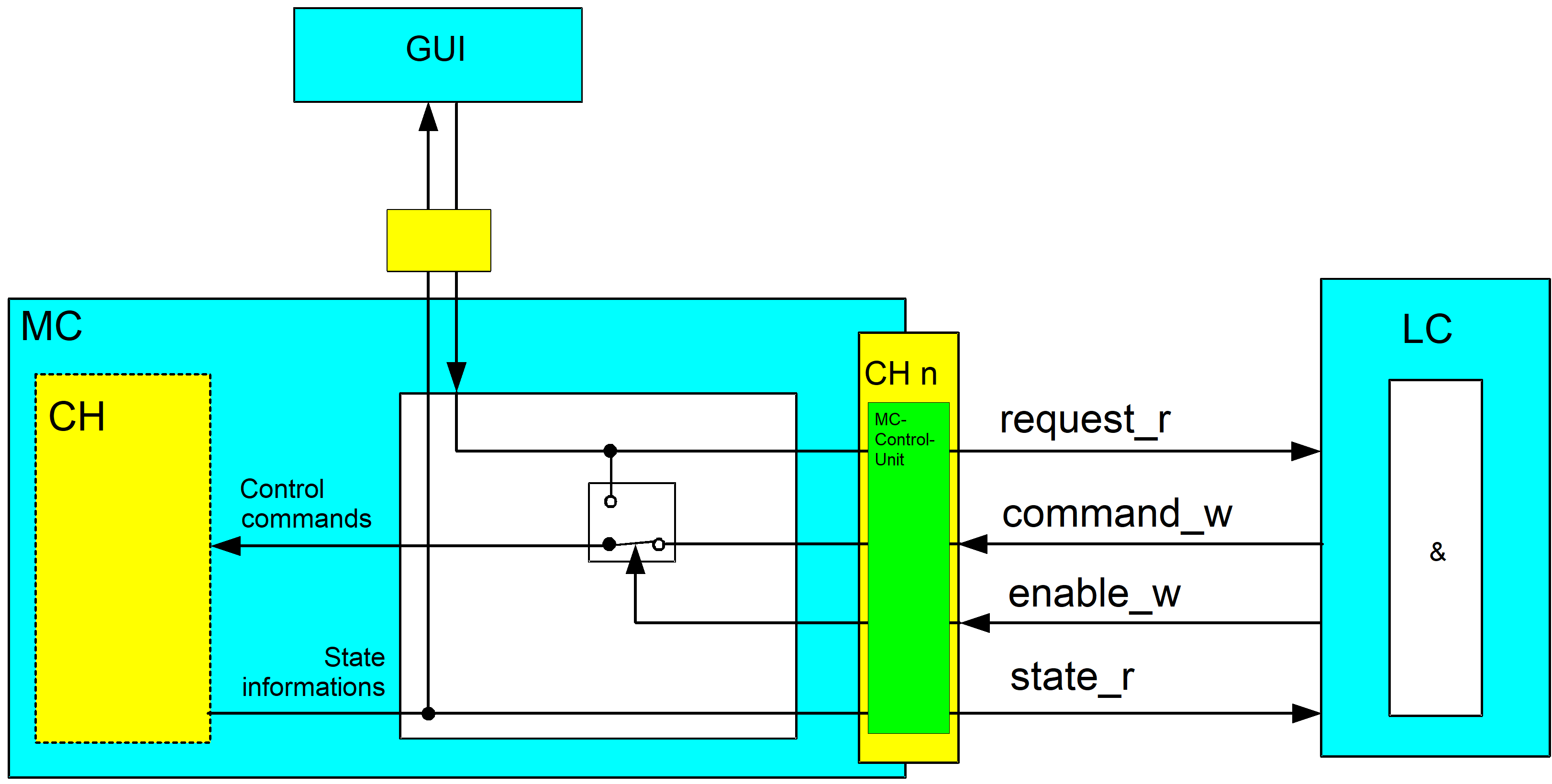
If commands from the GUI are to be redirected via the PLC, the PLC must assign the value TRUE to the enable_w element. The corresponding control commands from the GUI are then set to the request_r element of the MC control unit before processing. This means that the PLC has the option of allowing or rejecting this request from the GUI. If a GUI command is allowed by the PLC, the PLC must copy the command from element request_r to the element command_w.
Similarly, the PLC can directly send control commands to the CNC even without a prior job from a GUI by writing the element command_w.
The element state_r is used to check the success of the command. The CNC saves the status corresponding to the command in this element.
Notice

The element enable_w must be assigned the value TRUE in order to use a control unit.
If this is not the case, the control unit has no effect.
An MC control unit has the following structure:
TYPE MC_CONTROL_UNIT:
STRUCT
request_r < DATENTYP A >; (* data commanded by GUI *)
enable_w BOOL; (* PLC uses this command *)
command_w < DATENTYP A >; (* data commanded by the PLC *)
state_r < DATENTYP B >; (* acknowledgement sent by CNC *))
END_STRUCT
END_TYPE
Note:
- < DATA TYPE A > and < DATA TYPE B > may be identical.
- < DATA TYPE A > and < DATA TYPE B > may also be complex data structures besides the standard data types (e.g. BOOL, INT, UINT, ...).