Description
Definitions
The definition of how movement of an axis influences another axis is referred to as a coupling specification.
Below, the axis whose position is influenced by other axes on the basis of the coupling specification is referred to as the target axis.
Axes that influence other axes via coupling specifications are referred to as source axes.
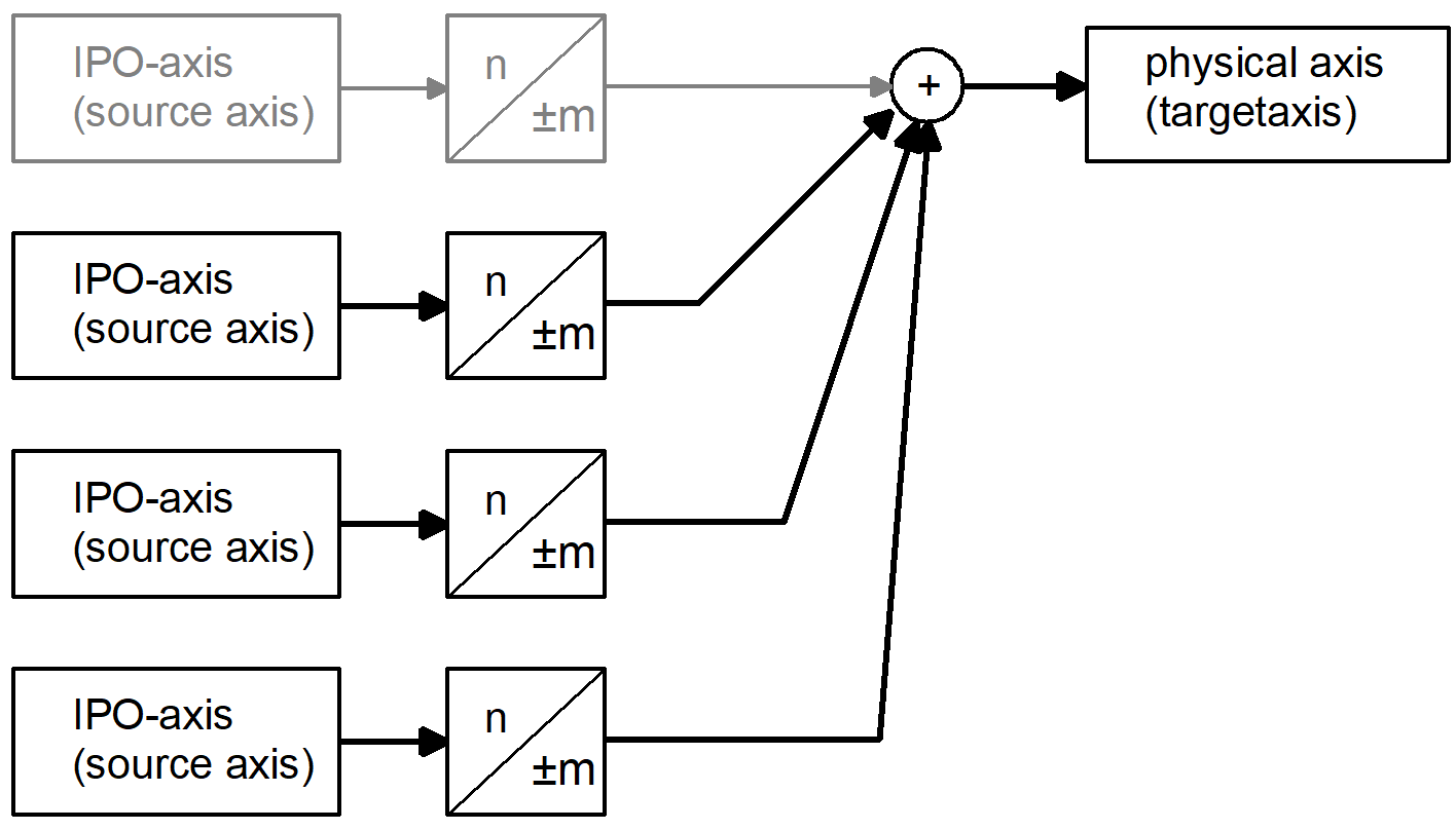
In this example several source axes act on a physical target axis. The interpolator axis that normally moves the target axis need not necessarily belong to the source axes.
Notice

A change in axis coupling must take place when all the axes involved are at standstill.
If this is not the case, the axis is stopped with error message ID 70200.
Standstill of all axes involved means that axis velocity must be 0. This affects both the target axis and all coupled source axes.
Notice
If a coupled axis is also programmed in the NC program, the target axis must be coupled to itself as source axis.
The coupling specification stipulates: source axis = target axis with coupling factor 1
As an alternative to axis coupling via the HLI, the coupling can also be parameterised and enabled using the NC command #GEAR LINK in the NC program.
Behaviour with command value request
Corresponding to the coupling instructions on drive level, an active gear coupling leads to an offset of the axis positions to the programmed command positions in NC channel. The axis positions and program coordinates are newly initialised at restart of program or by an explicitly programmed position request (#CHANNEL INIT [CMDPOS]). The ACS position (position on drive plane) is returned by default.
If the command value of the target axis is requested directly after activating an axis coupling, the returned value corresponds to the mechanical axis position.
The axis parameter P-AXIS-00436 defines the setting that the input coordinates of the gear coupling are recalculated by forward mapping when a command value request occurs.
If forward mapping of drive positions is activated with parameter P-AXIS-00436 the mapping is calculated by default relative to the activation position of the axis coupling..
The parameter P-AXIS-00460 can define the setting that the axis positions are regarded as absolute coordinates when a command value request occurs. In other words, it is assumed that the axis coupling is activated both for the master and for the slave axis at axis position 0.
Restrictions when using P-AXIS-00436
If the axis parameter P-AXIS-00436 is set, the target axis may not be coupled to itself as source axis either directly or indirectly.
When the coupling is activated, a check is made for coupling loops such as these. If one is discovered, the error message ID 70410 is output and the coupling is not executed.
Notice
When the parameters P-AXIS-00436 and P-AXIS-00460 are used, the channel must always be initialised.
Schematic of a coupling
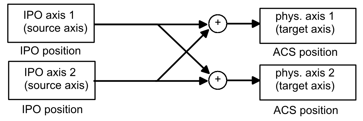
To calculate the IPO position of axis 2, the IPO position of axis 1 must already be known. The deadlock cannot be resolved and results in the output of error message ID 70410.
General
The coupling specifications of a target axis are defined via an axis-specific control unit of the HLI.
In this control unit of the target axis, the coupling specifications are defined by specifying the logical axis number of the source axis and the coupling mode. If coupling mode HLI_AXIS_COUPLING_FRACT is used, the coupling factor must also be specified as a fraction.
Several coupling specifications can be commanded. They are defined as an array in the commanded value of of the control unit. The indices of the array elements are within the interval [0 -HLI_AX_COUPLING_MAXIDX]
The entered coupling specifications are activated by setting an HLI signal.
After evaluating the coupling specifications and checking for errors, the NC kernel resets the trigger signal.
Activation
Mit axis_idx = [0..HLI_SYS_AX_MAXIDX]
coupl_idx = [0..HLI_AX_COUPLING_MAXIDX]
Axis-specific control unit of HLI:
gpAx[axis_idx]^.lr_mc_control.axis_coupling
Defining the logical axis number of the source axis:
gpAx[axis_idx]^.lr_mc_control.axis_coupling.command_w.desc[coupl_idx].ax_nr
Defining the coupling mode for this source axis:
gpAx[axis_idx]^.lr_mc_control.axis_coupling.command_w.desc[coupl_idx].mode
Definition of coupling factor:
gpAx[axis_idx]^.lr_mc_control.axis_coupling.command_w.desc[coupl_idx].fract_num
gpAx[axis_idx]^.lr_mc_control.axis_coupling.command_w.desc[coupl_idx].fract_denom
Activating trigger signal
gpAx[axis_idx]^.lr_mc_control.axis_coupling.command_w.semaphor_rw := TRUE
Programming of target axis
When axis couplings are used, all source axes acting on a target axis must be specified. If a target axis is also to be programmed in an NC program, a coupling specification must be defined for the logical axis number of the target axis on the HLI. For the programmed axis a coupling specification must be defined between its own source axis and its own target axis.
(See example 2)
Coupling modes
The following coupling modes can be specified for a coupling specification:
Coupling identifier | Value | Meaning |
HLI_AXIS_COUPLING_INACTIVE | 0 | The coupling specification is not active. All the following coupling specifications are also inactive. If the 1st coupling specification is defined as inactive, all coupling specifications are deactivated. |
HLI_AXIS_COUPLING_ZERO | 1 | Coupling factor 0 |
HLI_AXIS_COUPLING_DIRECT | 2 | The coupling factor between the source and target axis is 1. |
HLI_AXIS_COUPLING_MIRROR | 3 | The coupling factor between the source and target axis is -1. |
HLI_AXIS_COUPLING_FRACT | 4 | The coupling factor K is a fraction and is defined by a nominator and a denominator. |
Coupling factor
The coupling factor K is defined as
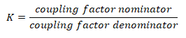
Defining the coupling factor:
the permissible value range for the coupling factor nominator is: [-32768 ... 32767]. A value of 0 has the same effect as using coupling mode HLI_AXIS_COUPLING_ZERO.
The permissible value range for the coupling factor denominator is [-32768 to 32767] excluding 0. A value of 0 causes the output of error message P-ERR-70396.
The absolute value of the coupling factor is limited to the value of HLI_AXIS_COUPLING_FACT_MAX. If the configured value for the coupling factor is greater than this value, the error message P-ERR-70397 is output.
Software limit switches
When the coupling mode HLI_AXIS_COUPLING_FRACT is used, the target axis command position resulting from the active couplings is monitored to the configured software limit switches (P-AXIS-00177/P-AXIS-00178) provided the axis is referenced.
Here, a check is made whether the axis can be stopped from the current velocity using the emergency stop deceleration (P-AXIS-00003) in front of the configured software limit switches. If the software limit switch is exceeded, the error message P-ERR-70195 is output and the axis is stopped.
Deactivation
The axis couplings of an axis can be deactivated by setting the coupling mode of the first coupling entry in HLI_AXIS_COUPLING_INACTIVE.
Example

Deactivating a coupling with several couplings on an axis
Coupling no. | Source axis | Target axis | Coupling mode | Coupling active |
1 | X2 | X2 | 2 | yes |
2 | X | X2 | 2 | yes |
3 | Y | X2 | 0 | No |
4 | Z | X2 | 2 | No |
In the example the third coupling is deactivated. The consequence is that all subsequent couplings are deactivated.
Status display
In the control unit the status of the axis with regard to axis couplings is indicated in the
gpAx[axis_idx]^.lr_mc_control.axis_coupling.state_r
structure.
The active_r structure element indicates whether an axis coupling is active for the axis. If a coupling is active, the element has the value TRUE.
When axis coupling is active, the couplings defined for this axis are indicated in the desc[] field.
An element of the desc[] field represents a coupling specification and consists of the following subelements.
- ax_nr: logical axis number of the source axis
- mode: the coupling mode defined for the source axis
Changing the axis coupling
Since it is only permitted to change an axis coupling if the target axis and all coupled source axes are at standstill, the PLC must first verify this when the coupling is changed.
In this case, for example, the current command velocity [10-3 mm/s or 10-3 degree/s] of the axis can be checked before the coupling is activated.
gpAx[axis_idx]^.lr_state.active_rev_r