Position controller-based axis couplings (#GEAR LINK)
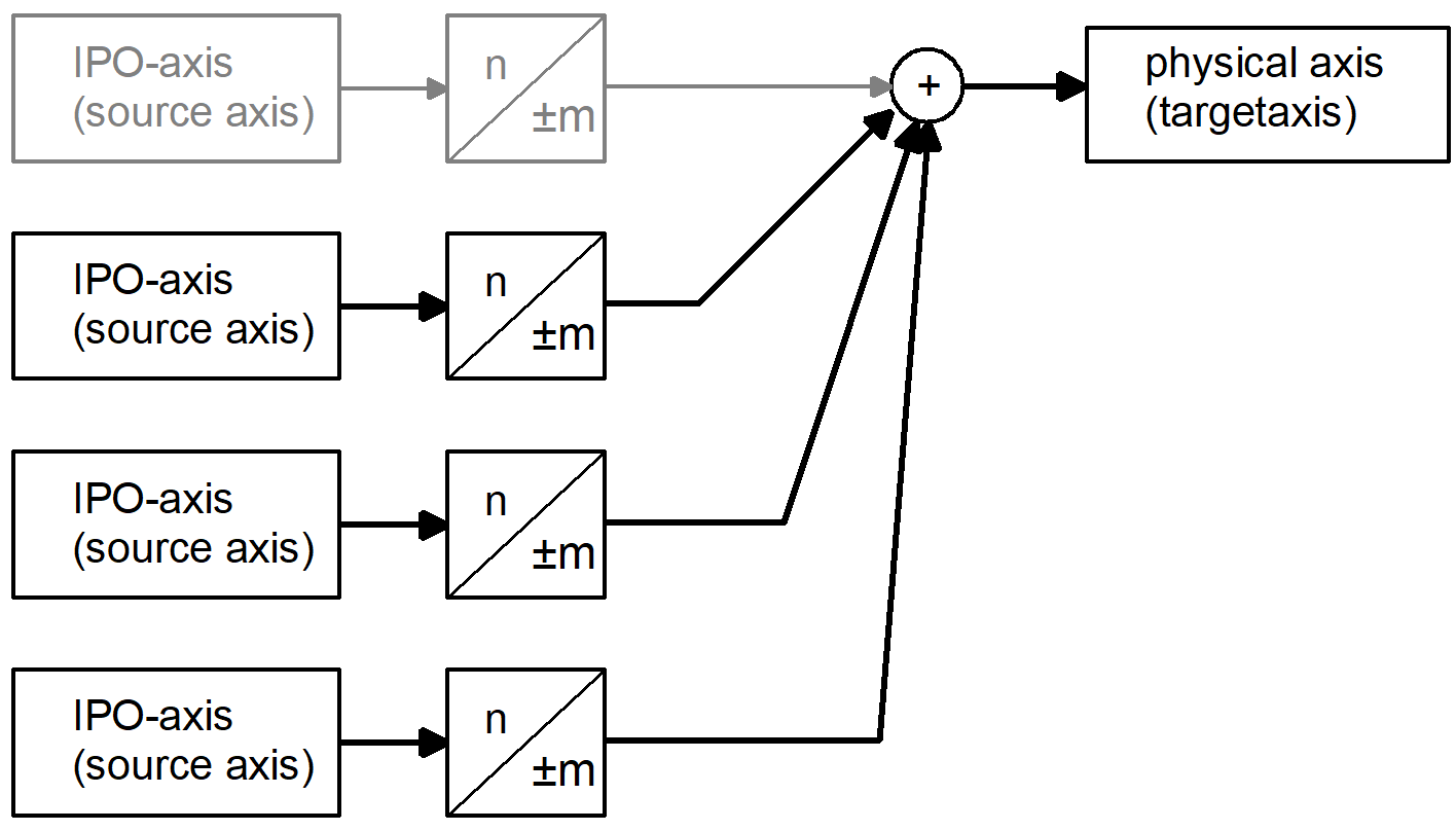
The motion of a target axis by a position controller-based axis coupling is influenced additively or even exclusively by the motions of other axes. The target axis is either an additional interpolator axis or a spindle.
Axes that influence a target axis via coupling specifications are referred to as source axes. The motion part of sources axes are weighted accordingly by defining specific factors. This permits the implementation of an electronic gear.
This function can be controlled by the HLI and is described in detail in [FCT-A9]. The NC command #GEAR LINK parameterises and enables this type of axis coupling, even in a subroutine.
Spindles can also be coupled.
Syntax of GEAR-LINK programming, parameterisation by axis names: |
#GEAR LINK [ TARGET=<axis_name> AX<i>=<axis_name> NUM<i>=.. DENOM<i>=.. {AX<i>=<axis_name> NUM<i>=.. DENOM<i>=..} [MODE=<mode>] [ACC=..] { \ } ] |
TARGET=<axis_name> | Name of coupling target axis |
AX<i>=<axis_name> | Name of source axis i where i =1 .. 4 |
| Caution: Only channel-specific axis names may be programmed as they are the only ones that are unique. |
NUM<i>=.. | Coupling factor NUM<i> / DENOM<i> for source axis i, numerator and denominator are negative or positive integers. |
MODE=<mode> | Mode for coupling/decoupling: DIRECT: Coupling requires all the axes involved to be at standstill (default). If this is not the case, stop occurs with error message ID 70200 SOFT: Soft coupling using slope; axes can move |
ACC=.. | Acceleration limit on the axis with coupling/decoupling in [mm/sec², inch/sec²]. If ACC is not specified, P-AXIS-00053 is used as default acceleration limit. |
\ | Separator ("backslash") for clear programming of the command over multiple lines. |
Syntax of GEAR-LINK programming, parameterisation by axis numbers: |
#GEAR LINK [ TARGETNR=.. AXNR<i>=.. NUM<i>=.. DENOM<i>=.. {AXNR<i>=.. NUM<i>=.. DENOM<i>=..} [MODE=<mode>] [ACC=..] [MCH] { \ } ] |
TARGETNR=. | Logical number of coupling target axes, positive integer |
AXNR<i>=.. | Logical number of source axis i where i =1 .. 4, positive integer |
| Caution: With cross-channel axis couplings using the keyword MCH, all logical axis numbers known in the system may be programmed as they are always unique in multi-channel systems. |
NUM<i>=.. | Coupling factor NUM<i> / DENOM<i> for source axis i; numerator and denominator are negative or positive integers. |
MODE=<mode> | Mode for coupling: DIRECT: Coupling requires all the axes involved to be at standstill (default). If this is not the case, stop occurs with error message ID 70200 SOFT: Soft coupling using slope; axes can move. If ACC is not specified, P-AXIS-00053 is used as default acceleration limit. |
ACC=.. | Acceleration limit on the axis with coupling/decoupling in [mm/sec², inch/sec²] |
MCH | Cross-channel axis couplings may be defined when MCH is set. Target and sources axes may then originate from different channels. Channel-specific monitors (active coupling at program end or on axis release) are not active. In DIRECT coupling mode, the user must ensure that axes outside the commanded channel are at standstill. Channel-specific and cross-channel axis couplings are managed separately. |
\ | Separator ("backslash") for clear programming of the command over multiple lines. |
Enabling a coupling
The following distinctions are possible:
- Enabling a coupling with parameters
- Enabling a previously parameterised coupling An error message is output if no coupling was parameterised.
Syntax of Enabling and parameterising in one step: |
#GEAR LINK ON [ .. ] |
Syntax of Enabling a previously parameterised coupling |
#GEAR LINK ON [ TARGET=<axis_name> | TARGETNR=.. [MCH] ] |
Disabling a coupling(s)
The following distinctions are possible:
- Disabling a coupling
- Disabling all axis couplings active in the channel, optionally with parameters
- Disabling all active axis couplings (cross-channel)
Syntax of Disabling a coupling |
#GEAR LINK OFF [ TARGET=<axis_name> | TARGETNR=.. [MCH] ] |
Syntax of Disabling all axis couplings active in the channel, optionally with parameters (as of V3.1.3081.13 or V3.1.3120.0): |
#GEAR LINK OFF ALL [ ACC=.. MODE=<mode> ] |
Syntax of Disabling all active axis couplings, cross-channel (as of V3.1.3081.13 or V3.1.3120.0): |
#GEAR LINK OFF ALL [MCH] |
The coupling state of an axis is determined in the NC program by the following variables
V.A.GEAR_LINK_ACTIVE.X does axis participate in a coupling? or V.A.GEAR_LINK_ACTIVE[i] |
V.G.GEAR_LINK_ACTIVE was an axis coupling commanded in the channel? |
Behaviour at program end and reset
If channel-specific axis couplings are active at program end, error message ID 70554 is output.
All active channel-specific axis couplings are disabled at reset.
Cross-channel axis couplings are disabled at reset if the target axis is in the reset channel or is not assigned to a channel at this time.
Programing Example

Defining and selecting a channel-specific coupling specification:
Parameterisation by axis name:
#GEAR LINK [TARGET=U AX1=X AX2=Y NUM1=1 DENOM1=2 NUM2=-1 DENOM2=1\
MODE=SOFT ACC=400]
:
TARGET=U ;Target axis is U AXIS
AX1=X ;Source axis 1 is X axis
NUM1=1 DENOM1=2 ;Coupling factor for X axis is NUM1/DENOM1=0.5
AX2=Y ;Source axis 2 is Y axis
NUM2=-1 DENOM2=1 ;Coupling factor Y axis is NUM2/DENOM2=-1
MODE=SOFT ;Soft coupling/decoupling
ACC=400 ;Acceleration limit on the axis at 400 mm/sec2
Enable coupling:
#GEAR LINK ON [TARGET=U]
Disable coupling:
#GEAR LINK OFF [TARGET=U]
Alternative parameterisation by axis number:
#GEAR LINK [TARGETNR=4 AXNR1=1 AXNR2=2 NUM1=1 DENOM1=1 NUM2=-1 \
DENOM2=1]
Enable coupling:
#GEAR LINK ON [TARGETNR=4]
Disable coupling:
#GEAR LINK OFF [TARGETNR=4]
Notice

If the target axis must still move through the channel itself, it must also be specified as the source axis:
#GEAR LINK [TARGET=U AX1=U AX2=Y NUM1=1 DENOM1=1 NUM2=-1 DENOM2=1]
Programing Example
Defining and selecting a cross-channel coupling specification:
Parameterisation by logical axis numbers:
#GEAR LINK [TARGETNR=25 AXNR1=1 AXNR2=40 NUM1=1 DENOM1=2 NUM2=-1\
DENOM2=1 MODE=SOFT ACC=400 MCH]
:
TARGETNR=25 ;Target axis is axis 25 in channel 2
AXNR1=1 ;Source axis 1 is axis 1 in active channel 1
NUM1=1 DENOM1=2 ;Coupling factor for axis 1 is NUM1/DENOM1=0.5
AXNR2=1 ;Source axis 2 is axis 40 in channel 4
NUM2=-1 DENOM2=1 ;Coupling factor for axis 40 is NUM2/DENOM2=-1
MODE=SOFT ;Soft coupling/decoupling
ACC=400 ;Acceleration limit on axis 25 at 400 mm/sec2
MCH ;Identifier for cross-channel coupling
Enable coupling:
#GEAR LINK ON [TARGETNR=25 MCH]
Disable coupling:
#GEAR LINK OFF [TARGETNR=25 MCH]
Programing Example
Coupling spindles
The initial situation involves 2 spindles S1 and S2 that must be available in the channel accordingly.
spindel[0].bezeichnung S1 ;P-CHAN-00007
spindel[0].log_achs_nr 4 ;P-CHAN-00036
# …
spindel[1].bezeichnung S2 ;P-CHAN-00007
spindel[1].log_achs_nr 5 ;P-CHAN-00036
;coupling the spindle S1 to spindle S1 with activation
N10 #GEAR LINK ON [TARGET=S2 AX1=S2 NUM1=1 DENOM1=1 AX2=S1 NUM2=5\
DENOM2=1]
N20 S1[M3 REV=1]
; …
;Stopping all source spindles
N70 S2 [M5]
N80 S1 [M5]
N90 #GEAR LINK OFF [TARGET=S2]
Programing Example
Disabling 2 active couplings
#GEAR LINK [TARGET=S AX1=X AX2=Y NUM1=1 DENOM1=2 NUM2=-1 DENOM2=1\
MODE=SOFT ACC=400]
#GEAR LINK [TARGET=X AX1=S AX2=Y NUM1=1 DENOM1=2 NUM2=-1 DENOM2=1\
MODE=SOFT ACC=400]
#GEAR LINK ON [TARGET=X]
#GEAR LINK ON [TARGET=S]
; …
#GEAR LINK OFF ALL [MODE=SOFT ACC=400]
M30