Description
P-CHAN-00039 | Axis-specific M functions |
Description | User-specific M functions programmed in DIN syntax are processed and executed channel-specific. If the user forces axis-specific processing for specific M functions, it is possible to configure them using this parameter so that they have an axis-specific effect. An axis name can be assigned to each M function on which it should act. Both path axes and spindle axes are permissible. |
Parameter | m_default_outp_ax_name[i] where i = 0 ... 999 (maximum number of M functions, |
Data type | STRING |
Data range | Maximum 16 characters (length of axis name, application-specific) |
Dimension | ---- |
Default value | * |
Remarks | Parameterisation example: The user-specific M function M10 is to act on the Z axis when programmed in the DIN syntax. The user-specific M function M11 is act on the S2 spindle when programmed in the DIN syntax m_default_outp_ax_name[10] Z m_default_outp_ax_name[11] S2 * Note: The default value of variables is a blank string. |
P-CHAN-00025 | Axis-specific H functions |
Description | User-specific H functions programmed in DIN syntax are processed and executed channel-specific. If the user wishes to force axis-specific handling for specific H functions, it is possible to configure them using this parameter so that they have an axis-specific effect. Each H function can be assigned an axis name on which it is to act. Both path axes and spindle axes are permissible. |
Parameter | h_default_outp_ax_name[i] where i = 0... 999 (maximum number of H functions, |
Data type | STRING |
Data range | Maximum 16 characters (length of axis name, application-specific) |
Dimension | ---- |
Default value | * |
Remarks | Parameterisation example: The user-specific H function H10 is to be programmed in DIN syntax to act on the Z axis. The user-specific H function H11 is to be programmed in DIN syntax to act on the S2 spindle axis. h_default_outp_ax_name[10] Z h_default_outp_ax_name[11] S2 * Note: The default value of variables is a blank string. |
P-CHAN-00052 | Enable mechanical gear change of main spindle |
Description | This parameter enables or disables gear changes for the main spindle. |
Parameter | main_spindle_gear_change |
Data type | BOOLEAN |
Data range | 0: Spindle gear changes disabled for the main spindle 1: Spindle gear changes enabled for the main spindle |
Dimension | ---- |
Default value | 0 |
Remarks | The M functions to select the gear speeds of the main spindle M40–45 are activated by the parameter P-CHAN-00052 in the channel parameter list. The M functions M40–45 can be freely used if gear changes are disabled. |
P-CHAN-00069 | Spindle control by PLC via channel specific interface |
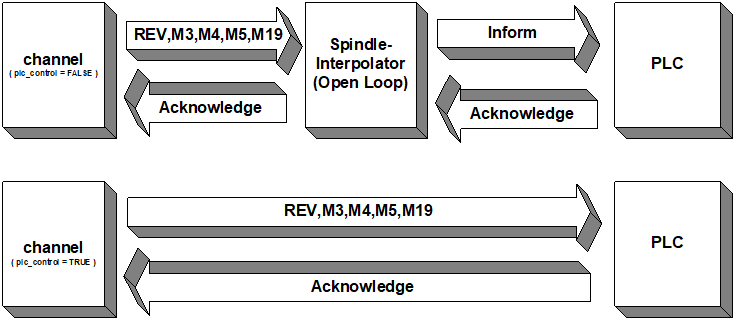
Description | This parameter is set to TRUE if a spindle is controlled directly by the PLC and not by a spindle interpolator in the NC channel. Note here that all synchronisations are no longer (spindle) axis-specific but are output and processed by the channel-specific HLI range. The axis-specific syntax for programming spindle commands is still allowed, but is limited to specifying the speed and the M functions M3/M4/M5/M19. |
Parameter | spindel[i].plc_control |
Data type | BOOLEAN |
Data range | 0/1 |
Dimension | ---- |
Default value | 0 |
Remarks |
|
P-CHAN-00098 | Switching the meaning of M functions M3/M4/M5/M19 |
Description | According to DIN66025, certain M functions have different meanings depending on the machining method and the type of machine. With metal-cutting machines (e.g. milling/turning/drilling), M3/M4/M5/M19 are permanently assigned to the spindle functions (direction of rotation, stopping, positioning). With machining methods such as plasma/laser cutting or wire erosion, the mentioned M functions are used to control other technology functions. To ensure free assignment, the meaning of the M functions M3/M4/M5/M19 can be switched over with this parameter. |
Parameter | spindle_m_fct_free |
Data type | BOOLEAN |
Data range | 0: M3/M4/M5/M19 are permanently assigned to the spindle M functions (default when spindles are configured). 1: M3/M4/M5/M19 are freely available for other technology functions. They must be defined in m_synch[i] in the channel parameters. Then the M functions are not spindle functions any more. |
Dimension | ---- |
Default value | 0 |
Remarks | When machining and cutting processes are combined on the same machine, it is possible to switch over the meaning of the M functions M3/M4/M5/M19 in the NC program using the variable V.SPDL.M_FCT_FREE [PROG]! |
Synchronisation definitions
P-CHAN-00041 | Synchronisation types of M functions |
Description | In the array m_synch[i], the synchronization type of the corresponding M function is defined. Here, the field index 'i' defines the number of the M function. The value indicates the synchronisation type of the M function, i.e. when a check is made for presence of a PLC acknowledgement. A motion is not executed, or is stopped at the latest towards the end of the block, if no acknowledgement has arrived from the PLC. The synchronisation type is defined as a string constant or a hexadecimal value. |
Parameter | m_synch[i] where i = 0 ... 999 (maximum number of M functions, application-specific) |
Data type | STRING |
Data range | See the table below. |
Dimension | ---- |
Default value | NOT_VALID * |
Remarks | M functions are consumption information and must be fetched (read) by the PLC. This also applies to M functions of the type MOS, MOS_TS, MEP_MOS and MET_MOS. Otherwise, this results in a blocked interface to the HLI in the CNC and as a consequence to an unexpected processing stop.
*Note: The default value for internal M functions (M0, M1, M2, M17, M29, M30, M3, M4, M19)
Caution: The following applies to synchronisation types with associated time and path-related pre-output (MET_SVS, MET_MOS, MEP_SVS, MEP_MOS): If one of these synchronisation types is later changed into one which requires no pre-output value, P-CHAN-00070 (m_pre_outp[i]) must be assigned to 0. Otherwise, a license error is generated in case of microjoints if this function is not licensed or not enabled (P-CHAN-00600; alternatively P-STUP-00060). The time calculation model for the pre-output time of M functions can also be defined for the synchronisation types MET_MOS and MET_SVS P-CHAN-00209. Example: m_synch[12] MVS_SVS 0x00000002
Note: Programming a UNS32 variable is permissible for downward compatibility reasons. Example: m_synch[12] 0x00000002 |
Constant | Value | Meaning |
NOT_VAILD | -1 | No valid M function |
NO_SYNCH | 0x00000000 | No output of M function to PLC |
MOS | 0x00000001 | Output of M function to PLC without synchronisation. If the M function is programmed within a motion block, the output of the M function is executed before the movement. M function must be fetched from PLC! |
MVS_SVS | 0x00000002 | Output of the M function to the PLC before the motion block, |
MVS_SNS | 0x00000004 | Output of the M function to the PLC before the motion block, |
MNS_SNS | 0x00000008 | Output of the M function to the PLC after the motion block, |
MNE_SNS | 0x00000020 | Output of M function to PLC after measurement event and removal of distance to go, |
MVS_SLM | 0x00004000 | Late synchronisation, output of M function to PLC within the block, synchronisation during transition to G01/G02/G03 (implicit synchronisation) |
MVS_SLP | 0x00008000 | Late synchronisation, output of M function to PLC within the block, synchronisation by NC command #EXPL SYN (explicit synchronisation) |
MOS_TS | 0x00040000 | Output of the M function to the PLC before motion block without synchronisation, |
MEP_MOS | 0x00100000 | Pre-output of M function with specified path, without synchronisation. |
MET_MOS | 0x00200000 | Pre-output of M function with specified time, without synchronisation. |
BWD_SYNCH | 0x00400000 | Synchronisation of M function during backward motion with MVS_SVS |
FWD_SYNCH | 0x00800000 | Synchronisation of M function during 'Simulated forward motion' based on the defined synchronisation type |
MEP_SVS | 0x01000000 | Output of M function with specified path, synchronisation before next block |
MET_SVS | 0x02000000 | Pre-output of M function with specified time, synchronisation before next block |
FAW_SYNCH | 0x10000000 | Decoding stop (Flush and Wait): Output of M function to PLC and stop of program decoding at block end until program run is completed. FAW_SYNCH can be set in addition to other synchronisation types. M functions with FAW_SYNCH may not be used when tool radius compensation (TRC), polynomial contouring and HSC mode are active. |
P-CHAN-00027 | Synchronisation type of H functions |
Description | The synchronisation type of the corresponding H function is defined in the array ‘h_synch[i]’. Here, the field index ‘i’ defines the number of the H function. This value indicates the synchronisation type of the H function, i.e. when a check is made for the presence of a PLC acknowledgement. A motion is not executed, or is stopped at the latest towards the end of the block, if no acknowledgement has arrived from the PLC. The synchronisation type is defined as a string constant or a hexadecimal value. |
Parameter | h_synch[i] where i = 0 999 (maximum number of H functions, application-specific) |
Data type | STRING |
Data range | See figure below |
Dimension | ---- |
Default value | NOT_VALID |
Remarks | H functions are consumption information and they must be fetched (read) from the PLC. This also applies to H functions of the type MOS, MEP_MOS and MET_MOS. Otherwise, this results in a blocked interface to the HLI in the CNC and as a consequence to an unexpected processing stop.
Caution: The following applies to synchronisation types with associated time and path-related pre-output (MET_SVS, MET_MOS, MEP_SVS, MEP_MOS): If one of these synchronisation types is later changed into one which requires no pre-output value, P-CHAN-00107 (m_pre_outp[i]) must be assigned to 0. Otherwise, a license error is generated in case of microwebs if this function is not licensed or not enabled (see P-CHAN-00600 Alternatively: P-STUP-00060) is inactive.
Example h_synch[12] MVS_SVS 0x00000002
Note: Programming a UNS32 variable is permissible for downward compatibility reasons. Example: m_synch[12] 0x00000002 |
P-CHAN-00045 | Synchronisation type for M03 |
Description | When the M03 function is used, the synchronisation type must be defined for the spindles used. The synchronisation type is defined as a string constant or a hexadecimal value. |
Parameter | spindel[i].m3_synch |
Data type | STRING |
Data range | |
Dimension | ---- |
Default value | NO_SYNCH |
Remarks | Parameterisation example: For a (position-controlled) spindle 'S1', the spindle-specific M function M03 is assigned the synchronisation type MVS_SVS. The PLC is also informed. spindel[0].bezeichnung S1 spindle[0].log_achs_no 6 spindel[0].s_synch MOS 0x00000001 spindel[0].m3_synch PLC_INFO | MVS_SVS 0x00020002 spindle[0].m4_synch PLC_INFO | MVS_SNS 0x00020004 spindle[0].m5_synch PLC_INFO | MVS_SVS 0x00020002 spindle[0].m19_synch MNS_SNS 0x00000008 Note: Programming a UNS32 variable is permissible for downward compatibility reasons. Example: spindel[0].m3_synch 0x00020002 |
P-CHAN-00047 | Synchronisation type for M04 |
Description | When the M04 function is used, the synchronisation type must be defined for the spindles used. The synchronisation type is defined as a string constant or a hexadecimal value. |
Parameter | spindel[i].m4_synch |
Data type | STRING |
Data range | |
Dimension | ---- |
Default value | NO_SYNCH |
Remarks | Parameterisation example: For a (position-controlled) spindle 'S1' the spindle-specific M function M04 is assigned the synchronisation type MVS_SNS. The PLC is also informed. spindel[0].bezeichnung S1 spindle[0].log_achs_no 6 spindel[0].s_synch MOS 0x00000001 spindel[0].m3_synch PLC_INFO | MVS_SVS 0x00020002 spindel[0].m4_synch PLC_INFO | MVS_SNS 0x00020004 spindle[0].m5_synch PLC_INFO | MVS_SVS 0x00020002 spindle[0].m19_synch MNS_SNS 0x00000008 Note: Programming a UNS32 variable is permissible for downward compatibility reasons. Example: spindel[0].m4_synch 0x00020004 |
P-CHAN-00049 | Synchronisation type for M05 |
Description | When the M05 function is used, the synchronisation type must be defined for the spindles used. The synchronisation type is defined as a string constant or a hexadecimal value. |
Parameter | spindel[i].m5_synch |
Data type | STRING |
Data range | |
Dimension | ---- |
Default value | NO_SYNCH |
Remarks | Parameterisation example: For a (position-controlled) spindle 'S1', the spindle-specific M function M05 is assigned the synchronisation type MVS_SVS. The PLC is also informed. spindel[0].bezeichnung S1 spindle[0].log_achs_no 6 spindel[0].s_synch MOS 0x00000001 spindel[0].m3_synch PLC_INFO | MVS_SVS 0x00020002 spindle[0].m4_synch PLC_INFO | MVS_SNS 0x00020004 spindel[0].m5_synch PLC_INFO | MVS_SVS 0x00020002 spindle[0].m19_synch MNS_SNS 0x00000008 Note: Programming a UNS32 variable is permissible for downward compatibility reasons. Example: spindel[0].m5_synch 0x00020002 |
P-CHAN-00043 | Synchronisation type for M19 |
Description | When the M19 function is used, the synchronisation type must be defined for the spindles used. The synchronisation type is defined as a string constant or a hexadecimal value. |
Parameter | spindel[i].m19_synch |
Data type | STRING |
Data range | |
Dimension | ---- |
Default value | NO_SYNCH |
Remarks | Parameterisation example: For a (position-controlled) spindle 'S1' the spindle-specific M function M19 is assigned the synchronisation type MNS_SNS. The PLC is also informed. spindel[0].bezeichnung S1 spindle[0].log_achs_no 6 spindel[0].s_synch MOS 0x00000001 spindel[0].m3_synch PLC_INFO | MVS_SVS 0x00020002 spindle[0].m4_synch PLC_INFO | MVS_SNS 0x00020004 spindle[0].m5_synch PLC_INFO | MVS_SVS 0x00020002 spindel[0].m19_synch MNS_SNS 0x00000008 Note: Programming a UNS32 variable is permissible for downward compatibility reasons. Example: spindel[0].m19_synch 0x00000008 |
P-CHAN-00070 | Path or time-related pre-output of M functions |
Description | This parameter is used in connection with M functions
The field index 'i' defines the number of associated M functions. The value of m_pre_outp[i] defines the path and time-related output point before actual processing of the M function on the path. |
Parameter | m_pre_outp[i] where i = 0 999 (maximum number of M functions, application-specific) |
Data type | UNS32 |
Data range | 0 ... MAX(UNS32) |
Dimension | 0.1 µm or µs |
Default value | 0 |
Remarks | The pre-output value can also be defined in the NC program [PROG//section V.G. variables]. Caution: If one of these synchronisation types is later changed into one which requires no pre-output value, P-CHAN-00070 (m_pre_outp[i]) must be assigned to 0. Otherwise, a license error is generated in case of microjoints if this function is not licensed or not enabled (see P-CHAN-00600 alternatively P-STUP-00060). Parameterisation example: The user-specific M functions M96 and M98 must be output to the SPS 10 mm before reaching the synchronisation position in the block sequence. The user-specific M functions M97 and M99 to SPS must be output 40 milliseconds before reaching the time of synchronisation in the block sequence.
# Definition of M functions and synchronisation types # ============================================ m_synch[96] 0x01000000 MEP_SVS m_synch[97] 0x02000000 MET_SVS m_synch[98] 0x00100000 MEP_MOS m_synch[99] 0x00200000 MET_MOS # # Definition of pre-output path, pre-output time #======================================= m_pre_outp[96] 100000 in 0.1µm m_pre_outp[97] 40000 in µs m_pre_outp[98] 100000 in 0.1µm m_pre_outp[99] 40000 in µs |
P-CHAN-00107 | Path or time-related pre-output of H functions |
Description | This parameter is used in connection with H functions
The field index 'i' defines the number of the associated H function. The value of h_pre_outp[i] defines the path and time-related output point before actual processing of the H function on the path. |
Parameter | h_pre_outp[i] where i = 0 999 (maximum number of H functions, application-specific) |
Data type | UNS32 |
Data range | 0 ... MAX(UNS32) |
Dimension | 0.1µm or µs |
Default value | 0 |
Remarks | The pre-output value can also be defined in the NC program [PROG//Chapter V.G. variables]. Caution: If the synchronisation type of an H function is later changed into one which requires no pre-output value, h_pre_outp[i] must be assigned to 0. Otherwise, a license error is generated in case of microwebs if this function is not licensed or not enabled (see P-STUP-00060). Parameterisation example: User-specific H functions H96 and H98 must be output to the PLC 10 mm before reaching the synchronisation position in the block sequence. The output of the user specific H functions H97 and H99 to the PLC must be executed 40 milliseconds before reaching the time of synchronisation in the block sequence.
# Definition of H functions and synchronisation types # ============================================ h_synch[96] 0x01000000 MEP_SVS h_synch[97] 0x02000000 MET_SVS h_synch[98] 0x00100000 MEP_MOS h_synch[99] 0x00200000 MET_MOS # # Definition of pre-output path, pre-output time #======================================= h_pre_outp[96] 100000 in 0.1µm h_pre_outp[97] 40000 in µs h_pre_outp[98] 100000 in 0.1µm h_pre_outp[99] 40000 in µs |
P-CHAN-00209 | Calculation model for M/H pre-output time |
Description | The time calculation function for the pre-output time can be controlled by means of this parameter for the M/H synchronisation types MET_SVS and MET_MOS. If the parameter is set to 0, the pre-output time is calculated independently of the actually active slope profile with a linear profile model. If a non-linear slope profile is active, the profile time is then only estimated. If the parameter is set to 1, the pre-output time is calculated depending on the active slope profile. Very precise time values are obtained by taking the ramp time into account in the non-linear profile. |
Parameter | m_h_pre_outp_time_calc_mode |
Data type | BOOLEAN |
Data range | 0: Time calculation model based on linear slope profile (default). 1: Time calculation model based on active slope profile |
Dimension | ---- |
Default value | 0 |
Remarks | The HSC slope type is not supported. |
P-CHAN-00212 | Activate residual path/time calculation with M/H code look ahead |
Description | This parameter activates the calculation and provision of residual path or time for the M/H synchronisation types MEP_SVS and MET_SVS. If the parameter is set to 1, the residual path or time is calculated after output of all M functions of synchronisation types MEP_SVS and MET_SVS relative to the synchronisation point. CNC objects* support access to the values. The look-ahead function waits until the current active synchronisation point is crossed before it changes to the next synchronisation point. |
Parameter | m_h_pre_outp_calc_value_to_go |
Data type | BOOLEAN |
Data range | 0: No calculation of residual path or time. As soon as all M functions of one synchronisation point are output, the function changes to the next synchronisation point (default). 1: M code look ahead with calculation of residual path or time. The function only changes to the next synchronisation point after the current active synchronisation point is crossed. |
Dimension | ---- |
Default value | 0 |
Remarks | * Accesses to CNC objects: Path to synchronisation point: [0.1 µm] Index Group: 0x21301 Offset: 0x27 Time to synchronisation point: [1 µs] Index Group: 0x21301 Offset: 0x28 |
P-CHAN-00274 | Number of NC blocks at M/H code look ahead |
Description | This parameter increases the number of NC blocks for look ahead for M/H synchronisation types MEP_SVS and MET_SVS. By default the number of blocks is 50. The increased number of blocks causes an increased cycle time in the real-time part of the CNC. |
Parameter | m_h_pre_outp_nbr_block |
Data type | UNS32 |
Data range | 50 ≤ P-CHAN.00274 ≤ 200 |
Dimension | ---- |
Default value | 50 |
Remarks | Configuration example:
m_h_pre_outp_nbr_block 100 #100 blocks M code look ahead # P-CHAN-00653 - Large Look-Ahead buffer configuration.interpolator.parameter 100 # P-CHAN-00655 – Activate customer-specific configuration.interpolator.fct_enable[0] FCT_LOOK_AHEAD_CUSTOM
configuration.channel[0].interpolator.parameter 100 |
P-CHAN-00033 | Default setting for 'Late synchronization at program end' at program start |
Description | This parameter is used in conjunction with synchronisation types MVS_SLM and MVS_SLP (Late Sync). It defines the reaction to open Late Sync M functions at program end. This may occur if there is no G01 block in the NC program until program end (with MVS_SLM) or if no explicit synchronisation was programmed (with MVS_SLP). |
Parameter | prog_start.late_sync_ready |
Data type | BOOLEAN |
Data range | 0: Open Late Sync M functions at the end of the program are still active the next time the program is started. This means that one or several Late Sync M functions of the first NC program are only triggered by a Late Sync event (G01 block or #EXPL SYN) of the second NC program. 1: At program end, the program waits until all open Late Sync M functions are acknowledged by the PLC. |
Dimension | ---- |
Default value | 0 |
Remarks | Parameterisation example: At program end, the program waits until all open Late Sync M functions are acknowledged by the PLC. prog_start.late_sync_ready 1 |
Production time calculation
P-CHAN-00040 | Timeout / process times of M functions for machining time calculation |
Description | The timeout times of M functions are set in the array ‘m_prozess_zeit[i]’. The field index ‘p’ defines the number of the M function. If the calculation of machining time is activated, the process times of the M functions are specified in this array. |
Parameter | m_prozess_zeit[i] where i = 0 999 (maximum number of M functions, |
Data type | UNS32 |
Data range | 0 ≤ m_prozess_zeit ≤ MAX(UNS32) |
Dimension | µs |
Default value | 0 |
Remarks | This element is currently only used to calculate machining time. Parameterisation example: The timeout and process time of M function 'M15' to specified as 0.5 s. m_prozess_zeit[15] 500000 |
P-CHAN-00026 | Timeout / process times of H functions for machining time calculation |
Description | The timeout times of H functions are specified in the array ‘h_prozess_zeit[i]’. The field index ‘i’ defines the number of the H function. If the calculation of machining time is activated, the process times of H functions are specified in this array. |
Parameter | h_prozess_zeit[i] here i = 0... 999 (maximum number of H functions, application-specific) |
Data type | UNS32 |
Data range | 0 < P-CHAN-00026 < MAX(UNS32) |
Dimension | [µs] |
Default value | 0 |
Remarks | This element is currently only used to calculate machining time. Parameterisation example: The following example specifies the timeout and process time of H function 'H1' to 20 ms. h_prozess_zeit[15] 20000 |
P-CHAN-00080 | Timeout and process time of the spindle function S for the machining time calculation |
Description | This parameter specifies the timeout and the process time of a spindle S function when the machining time calculation is activated. |
Parameter | spindel[i].s_prozess_zeit |
Data type | UNS32 |
Data range | 0 < s_prozess_zeit < MAX(UNS32) |
Dimension | µs |
Default value | 0 |
Remarks | Currently, the parameter is only used to calculate machining time. Parameterisation example: The process time of the spindle function is defined as 1 s for an ‘S1’ spindle. spindel[0].bezeichnung S1 spindel[0].log_achs_nr 6 : spindel[0].s_prozess_zeit 1000000 spindel[0].m3_prozess_zeit 1000000 spindel[0].m4_prozess_zeit 1000000 spindel[0].m5_prozess_zeit 1500000 spindel[0].m19_prozess_zeit 2000000 |
P-CHAN-00044 | Timeout and process time of M03 for calculation of machining time |
Description | This parameter specifies the timeout and the process time of the M function M03 when the machining time calculation is activated. |
Parameter | spindel[i].m3_prozess_zeit |
Data type | UNS32 |
Data range | 0 < m3_prozess_zeit < MAX(UNS32) |
Dimension | µs |
Default value | 0 |
Remarks | Currently, the parameter is only used to calculate machining time. Parameterisation example: The process time for M03 is set to 1s for the spindle 'S1'. spindel[0].bezeichnung S1 spindel[0].log_achs_nr 6 : spindel[0].s_prozess_zeit 1000000 spindel[0].m3_prozess_zeit 1000000 spindel[0].m4_prozess_zeit 1000000 spindel[0].m5_prozess_zeit 1500000 spindel[0].m19_prozess_zeit 2000000 |
P-CHAN-00046 | Timeout and process time of M04 to calculate machining time |
Description | This parameter specifies the timeout and the process time of the M function M04 when the machining time calculation is activated. |
Parameter | spindel[i].m4_prozess_zeit |
Data type | UNS32 |
Data range | 0 < m4_prozess_zeit < MAX(UNS32) |
Dimension | µs |
Default value | 0 |
Remarks | Currently, the parameter is only used to calculate machining time. Parameterisation example: The process time for M04 is set to 1s for the spindle 'S1'. spindel[0].bezeichnung S1 spindel[0].log_achs_nr 6 : spindel[0].s_prozess_zeit 1000000 spindel[0].m3_prozess_zeit 1000000 spindel[0].m4_prozess_zeit 1000000 spindel[0].m5_prozess_zeit 1500000 spindel[0].m19_prozess_zeit 2000000 |
P-CHAN-00048 | Timeout and process time of M05 to calculate machining time |
Description | This parameter specifies the timeout and the process time of the M function M05 when the machining time calculation is activated. |
Parameter | spindel[i].m5_prozess_zeit |
Data type | UNS32 |
Data range | 0 < m5_prozess_zeit < MAX(UNS32) |
Dimension | µs |
Default value | 0 |
Remarks | Currently, the parameter is only used to calculate machining time. Parameterisation example: For spindle 'S1' the process time for M05 is defined as 1 s. spindel[0].bezeichnung S1 spindel[0].log_achs_nr 6 : spindel[0].s_prozess_zeit 1000000 spindel[0].m3_prozess_zeit 1000000 spindel[0].m4_prozess_zeit 1000000 spindel[0].m5_prozess_zeit 1500000 spindel[0].m19_prozess_zeit 2000000 |
P-CHAN-00042 | Timeout and process time of M19 to calculate machining time |
Description | This parameter specifies the timeout and the process time of the M function M19 when the machining time calculation is activated. |
Parameter | spindel[i].m19_prozess_zeit |
Data type | UNS32 |
Data range | 0 < m19_prozess_zeit < MAX(UNS32) |
Dimension | µs |
Default value | 0 |
Remarks | Currently, the parameter is only used to calculate machining time. Parameterisation example: The process time for M19 is set to 2s for the spindle 'S1'. spindel[0].bezeichnung S1 spindel[0].log_achs_nr 6 : spindel[0].s_prozess_zeit 1000000 spindel[0].m3_prozess_zeit 1000000 spindel[0].m4_prozess_zeit 1000000 spindel[0].m5_prozess_zeit 1500000 spindel[0].m19_prozess_zeit 2000000 |
P-CHAN-00600 | Defining functionalities for path preparation. |
Description | This parameter defines the individual functionalities for path preparation. The individual functions can be enabled or disabled for testing or for performance reasons. |
Parameter | configuration.path_preparation.function |
Data type | STRING |
Data range | |
Dimension | ---- |
Default value | FCT_DEFAULT |
Remarks | Parameter is available as of the following Builds: V2.11.2040.04 ; V2.11.2810.02 ; V3.1.3079.17 ; V3.1.3107.10 Functions can be defined in P-CHAN-00605 and P-CHAN-00606 depending on the machining mode. |