Extended programming (#MEAS, #MEAS DEFAULT, #MEAS PREPARE)
Alternatively to the #MEAS MODE command, the following command offers additional measuring parameters. The selected parameter settings remain valid until program end. When the program is restarted, the default settings in the configuration lists are again valid. To be able to change the measurement parameters of an axis, it must be identified as a measurement axis (i.e. the axis parameter P-AXIS-00118 must be set to 1:
Syntax: |
#MEAS [ [TYPE=..] [ERR_NO_SIGNAL=..] [ [SIMU_OFFSET=..] | [TRIGGER] ] | [ {AX=<axis_name> | AXNR=..} [SIGNAL=<ident>] [EDGE=<ident>] [INPUT=..] [G107 | G108] ] ] |
TYPE=.. | New measurement type as described in Section Measuring functions. This measurement type is valid until the next change or until program end. |
ERR_NO_SIGNAL=.. | Reaction to undetected probe signal: 0: no error message 1: Error message when measurement run is deselected (default) |
SIMU_OFFSET=.. | This keyword is only effective in particular for a measuring simulation in connection with the axis parameter P-AXIS-00112=4. The value in [mm, inch] offsets the simulated default measuring point relative to the path motion based on the programmed target points. The measurement type 2 shifts the default measuring point in a positive or negative direction by SIMU_OFFSET. Any additional offset by the axis parameter [2]P-AXIS-00114 is not considered here. |
TRIGGER | Triggering a programmed probe signal. Only used in conjunction with the global block edge banding function G107/G108. Is only effective if P-CHAN-00257 is active. |
Notice

SIMU_OFFSET and TRIGGER are exclusive and may not be programmed in combination with the other axis-
specific keywords.
AX=<axis_name> | Name of the axis whose measurement parameters are to be changed. The axis must be configured as a measurement axis. |
AXNR=.. | Logical number of the axis whose measurement parameters are to be changed. The axis must be configured as a measurement axis, positive integer |
SIGNAL=<ident> | Name of the probe signal source used for the measurement (see P-AXIS-00516). Valid identifiers: PLC:Probe signal via PLC DRIVE: Probe signal via drive position latch FIXED_STOP: Probe signal by moving to fixed stop PLC_FIRST_EVENT: Probe signal by PLC. Measurement run terminates when one axis receives the measuring event PLC_EXT_LATCH_CONTROL: Measure with measuring interval for external hardware (see [HLI//Measuring with measuring interval for external hardware]) EXT_PROBE_WITH_DRIVE: Measure with measuring interval for external hardware, measuring point via drive interfaces (see [HLI//Measuring with measuring interval for external hardware]) |
| |
EDGE=<ident> | Relevant measurement edge, (see P-AXIS-00518). Valid identifiers: POS: Positive (rising) measurement edge NEG: Negative (falling) measurement edge |
INPUT=.. | Name of the drive measurement input used for the measurement (see P-AXIS-00517). For probe signal DRIVE: 1: 1st measurement input 2: 2nd measurement input For probe signal PLC_EXT_LATCH_CONTROL: 1 .. 255: Channel number of measurement input of the external measuring hardware |
G107 | Deselect edge banding function for this axis, i.e. no measured value is latched for this axis with edge banding. |
G108 | Select edge banding function for this axis. The precondition is that the "edge banding " function must be active for the axis in the axis parameters (see P-AXIS-00098). |
The #MEAS command provides the following extensions for a modal measurement run (over several motion blocks) in conjunction with the edge banding function (measurement type 8).
Syntax: | |
#MEAS [ON | OFF] [ [<measurement_parameter>] ] | |
ON | Select measurement run for measurement type 8 All set or programmed axes are then measured in the following motion blocks. |
OFF | Deselect measurement run for measurement type 8 |
Syntax: | |
#MEAS DEFAULT [ [ {AX=<axis_name> | AXNR=..} ] | |
DEFAULT | Reset the axis-specific (AX, AXNR) parameter settings (SIGNAL, EDGE, INPUT, G107/G108) changed by the #MEAS command. The measurement settings of the axis parameter list are effective again. |
With some measurement methods, it may be better to start the initialisation earlier, as this requires a certain amount of time. For example, this includes the signal sources EXT_PROBE_WITH_DRIVE or DRIVE, if the measurement has to be prepared with S-0-0170. In these cases, #MEAS PREPARE can be used to initialise the measurement earlier so that there is no need to wait at the start of the measurement block. This makes sense if the initialisation of the measurement takes a long time, e.g. with an external radio probe. In this case, the user must ensure that there is sufficient time between #MEAS PREPARE and the actual measurement block to complete measurement preparations depending on the measurement method.
Syntax: | |
#MEAS PREPARE [ [ {AX=<axis_name> | AXNR=..} ] | |
PREPARE | Preparing a measurement run depending on the parameterised measurement method, (e.g. premature activation or initialisation of a touch probe). |
Notice
The measurement edge (EDGE) and measurement input (INPUT) cannot be changed for SERCOS drives with position latch in the drive (SIGNAL=DRIVE) because this also requires parameter changes in the drive for this purpose.
Programing Example

Setting measurement parameters:
Selecting a different measurement type:
N100 #MEAS [TYPE=2]
Setting measurement positions for the measurement simulation for measurement type 2:
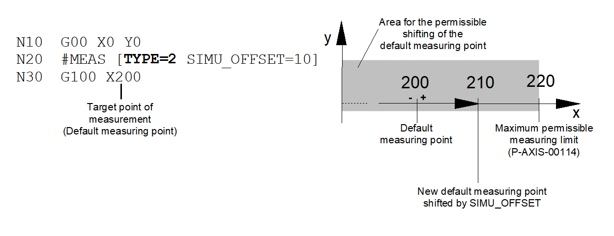
For all other measurement types only an offset in negative direction (opposite to the path motion direction) is possible.

Activate measurement by moving to fixed stop for X and Y axes:
N100 #MEAS [AX=X AX=Y SIGNAL=FIXED_STOP]
Activate probe signal via PLC to negative edge:
N100 #MEAS [AXNR=1 SIGNAL=PLC EDGE=NEG]
Deactivate edge banding function for Y and Z axes:
N100 #MEAS [AX=Y AX=Z G107]
Restore the measurement settings in the axis parameters for all path axes:
N100 #MEAS DEFAULT
Restore the measurement settings in the axis parameters for X axis:
N100 #MEAS DEFAULT [AX=X]
Modal measurement run with all measurement axes:
N5 #MEAS [TYPE=8]
N10 G01 X100 Y100 F1000
N20 G01 Z200
N30 G01 X200 Y200
N40 #MEAS OFF
Modal measurement run with measurement in X and Y axes, probe signal via PLC, leading edge, no error message if probe signal not detected
N5 #MEAS ON [TYPE=8 AX=X AX=Z SIGNAL=PLC EDGE=POS ERR_NO_SIGNAL=0]
N10 G01 X100 Y100 Z10 F1000
N20 G01 X200 Y150 Z25
N30 #MEAS OFF
Preparing a touch probe for a measurement run
N5 G00 X0
N10 G00 X500
N20 #MEAS PREPARE [AXNR=1] ;preparing the measurement run
:
Nxx ;further program actions
:
N120 G00 X700 N130 G00 X1000
N130 G100 X1300 F1000 ;start of measurement run