Escape channel
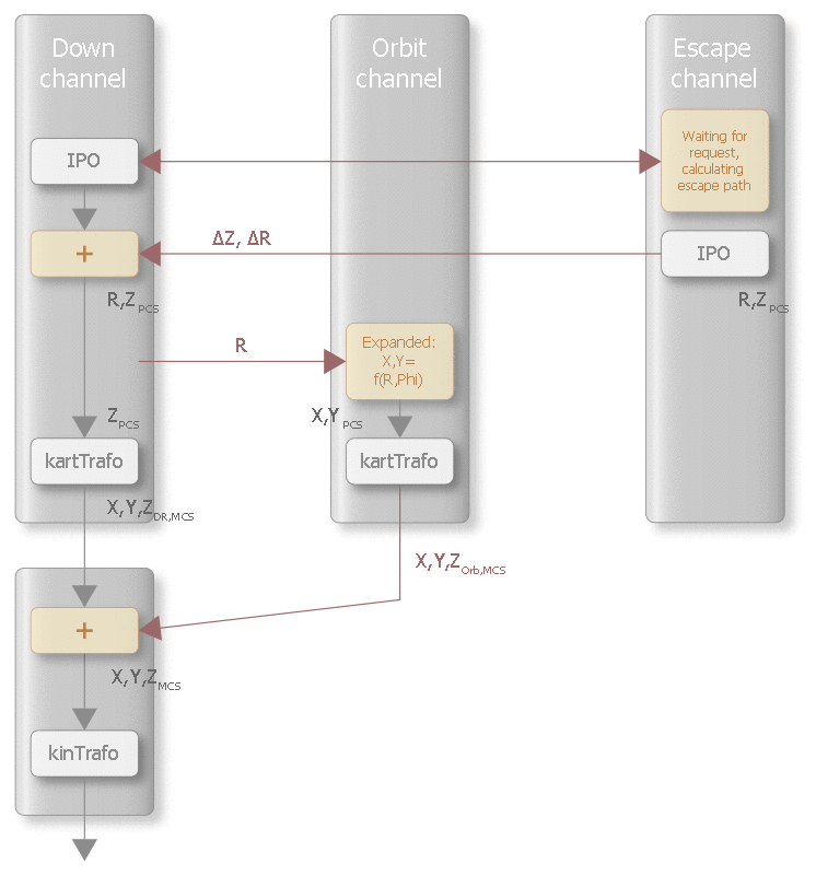
The escape motion of the electrode is executed in the escape channel and superimposed on the motion of the down channel.
The figure below shows the relationship between channel interfaces and the superimpositions ∆Z and ∆R viewed from the down channel:

The escape channel must be initialised by an NC program that contains the following:
- The path erosion geometry of the down channel
- Initialisation of the interface to the down channel
At the end of the program, an escape can be commanded by specifying a negative external velocity on the corresponding HLI interface (Specified external path velocity) control unit). The escape motion is calculated for each command based on the current position in the down channel.
Various escape strategies are implemented, each of which results in a different escape path:
- Flat - plane strategy
- Alpha - Alpha angle strategy
- Point - point strategy
- Bisector - angle bisector strategy
In all escape strategies except for path erosion, the tool is first retracted to the origin of the current coordinate system. By default, the origin must be located at the end point of the path erosion geometry. Then, if path erosion was programmed ahead of it, the escape strategy continues with this geometry. This special case is described in Changing the escape point.
By superimposing the positions of the down and escape channels, the escape channel can be used to adjust the gap between the electrode and the workpiece to meet the process requirements, provided the appropriate escape strategy is selected. The external velocity required for this in the escape channel is specified by the spark generator.