Description
Principle
Position lag is caused by control system delay in speed, acceleration and jerk in the position controller with respect to the command variable calculated in the interpolator.
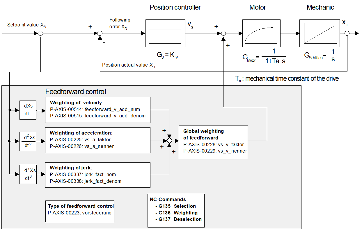
Feedforward control calculates the theoretical position lag to be set in the interpolator and which would result from the current speed, acceleration and jerk. From this, it calculates the command speed value vVorsteuerung which is then added to the position controller output (see Fig. “Block diagram of conventional feedforward control”). This additional command value can be weighted with a factor.
The position lag expected from the axis speed Δsv is obtained from the equation:
Δsv = v/Kv
The position lag expected from constant acceleration Δsa is obtained from:
Δsa = a*Ta/Kv
The position lag expected from constant jerk Δsj results from:
Δsj = j+Ta/Kv2
Where Ta is the mechanical time constant of the drive.
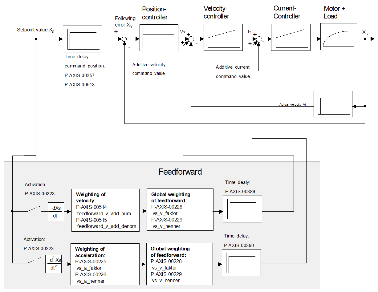
Alternatively the command velocities and accelerations calculated in the CNC controller can be transferred as additive speed and torque command values to the drive controller and fed into the appropriate control loops as additive command values (see figure below).
Feedforward control modes
Based on the cause of the position lag, the control system distinguishes between the following feedforward control modes
- Velocity feedforward control
- Acceleration feedforward control and
- Jerk feedforward control.
All feedforward control modes can be enabled or parameterised independently of one another.
Feedforward control for spindles
In the case of spindles, feedforward control is particularly necessary for thread tapping with endlessly rotating spindles since an ideal machining result is obtained by maintaining the specified command values with as few position lags as possible on both path axes and spindles.
Activation
The parameter P-AXIS-00223 enables feedforward control for each axis or spindle. When the corresponding bits are set, the feedforward control modes are selected and further control information is also activated. The feedforward control mode is selected in the NC program.
Attention

Note that the axes may overshoot when feedforward control is enabled.
Therefore, please be careful when parameterising feedforward control. Set the correct weighting factors in the axis parameter lists and in the NC program.
Weighting
The resulting feedforward control parameter can be weighted with 2 axis-specific factors. The parameters P-AXIS-00228 and P-AXIS-00229 weight the entire feedforward control process.
Weightingvorsteuerung = P-AXIS-00228/P-AXIS-00229
Acceleration feedforward control can also be weighted by a real-time constant Ta which is defined by the parameters P-AXIS-00225 and P-AXIS-00226.
Ta = P-AXIS-00225/P-AXIS-00226
Jerk feedforward control can also be weighted by a factor
WeightingRuckvorsteuerung = P-AXIS-00337/P-AXIS-00338
which is defined from the parameters P-AXIS-00337 and P-AXIS-00338.
Notice

Empirically, the entire feedforward control can be weighted by a factor in the range of 0.7–1. At values >1 the axis is ahead of and the accuracy of the contour is falling off.
Parameterisation for PROFIdrive drives
PROFIdrive drives require the following additional parameters which must be set in the axis parameter lists:
- P-AXIS-00092: Position controller increments per revolution
- P-AXIS-00165: time offset of feedforward control parameters
With PROFIdrive drives, the parameter P-AXIS-00223 selects how to transfer the calculated feedforward control value to the drive:
- P-AXIS-00223, Bit 9 = 0: The feedforward control value is calculated in the control deviation (XERR – signal No. 25) as a position lag.
- P-AXIS-00223, Bit 9 = 1: The feedforward control value is included in the speed command value as a speed (NSOLL_B – signal No. 7).
Attention
SERCOS drives
With SERCOS drives, if feedforward control is to be implemented in the NC control system and not in the drive, the Kv factor in the axis parameter list must be set identical to the Kv factor of the SERCOS drive (IDN: (S-0-0104).
Notice
With SERCOS drives, feedforward control is normally implemented in the drive itself and is set with the following parameters:
IDN: S-0-0296: Velocity feed forward gain
IDN: S-0-0348: Acceleration feedforward gain