Feed forward
Spindle position lag can be minimised by using speed and acceleration feedforward control.
Spindle feedforward control is required especially to tap threads with an endlessly rotating spindle since both the path axes and the spindle must keep to the specified setpoints as far as possible without position lag if a good machining result is to be achieved.
Conventional feedforward control
This type of feedforward control is only possible for conventional drives and for drive simulation.
The theoretical position lag is then calculated based on the current speed and acceleration and is added to the setpoint specified by the interpolator. The expected position lags can be calculated by the relation
|
|
|
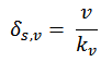
for constant speed and
|
|
|
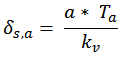
for constant acceleration. Ta is the drive time constant which can be set in the axis parameter list P-AXIS-00225/ P-AXIS-00226.
Maintaining the permissible axis acceleration values is taken into account when the feedforward control variable is added to the specified setpoint.
The condition for the described equations is use of a P position controller whose velocity gain for linear axes
|
|
|

or speed gain for rotation axes
|
|
|

are essentially defined by the drive dynamics.
Path fidelity
If all axes of a system have the same kv factor, there are no deviations from the specified path, neither with straight ahead nor circular motion after stabilisation. A position lag is only executed according to the equations described above.
Sampling time and prefiltering
When velocity v and acceleration a are derived from differentiation of the distance, make sure that sampling times are sufficiently long to minimise undesirable quantisation noise. Improved response is also achieved by prefiltering v and a. For this reason, several values of v and a are averaged linearly.
Settings
Feedforward control leads to an increase in dynamic acceleration stress and an increase in control ranges. An improvement in path fidelity by feedforward control is only possible with position controller settings whose velocity or speed gain is less than the optimum values required for response to setpoint changes since otherwise there is an extreme inclination to overshoot.
Coupling in feedforward control
Activating or deactivating feedforward control during the motion may lead to oscillations. This is why it is necessary to use 'soft' coupling for feedforward control. This includes the maximum permitted axis acceleration values or maximum jerk (e.g. for the non-linear 'slope' function). This permits activation or deactivation of feedforward control as required at block boundaries without interrupting the motion. Wear and tear on the drive and also on the mechanics of the machine tool can be reduced by activating feedforward control for paths which require precise machining.
Notice

Further information on the subject of feedforward control and parameterisation is contained in the description of functions [FCT-D2].
Programming
S[G135] Spindle feedforward control on
S[G136] Specify weighting
S[G137] Spindle feedforward control off
Notice
With digital drive systems (e.g. SERCOS), feedforward control can be activated and parameterised in the drive.
After homing and positioning with M19, the spindle is always stopped with exact stop.