Jerk-limited default acceleration profile
Description and properties
Both for
- axes in the path group and for
- independent axes
a jerk-limited acceleration can be selected with a trapezoidal or sine-square profile.
Parameterisation is identical and axis-specific for both profiles. As opposed to the trapezoidal profile, the sine-square profile permits softer acceleration and deceleration.
With jerk-limited acceleration, the path motion is controlled so that axis-specific accelerations do not suffer any abrupt changes.
For HSC contour machining, a special jerk-limited slope can be selected to optimise block global acceleration.
These profiles must be used with machine constructions that are subject to critical vibrations. The ramp times for building up and reducing acceleration should only be set as high as necessary and as low possible because these parameters have a considerable influence on positioning times.
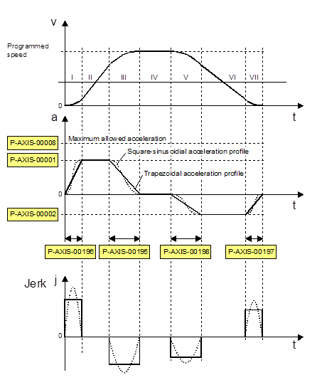
The jerk-limited acceleration profile can be displayed in 7 segments (see figure below “Parameters with jerk-limited acceleration profile”).
I | Velocity increase at increasing acceleration to a maximum acceleration value within a specified time. |
II | Velocity increase at constant acceleration. |
III | Velocity increase at decreasing acceleration down to the acceleration value 0 within a specified time. |
IV | Phase at constant velocity, acceleration 0 |
V | Velocity decrease at increasing deceleration to a maximum deceleration value within a specified time. |
VI | Velocity decrease at constant deceleration. |
VII | Velocity decrease at decreasing deceleration down to the deceleration value 0 within a specified time. |
The parameters in segments I, III, V and VII determine the axis jerk caused by the acceleration profile.
Advantages
The advantage of jerk-limited acceleration profiles are:
- Better use of available machine dynamics (e.g. positioning in rapid traverse)
- Reduced wear and tear on mechanical systems by avoiding impacts
- Low excitation of vibrations
- Improved possibility of parameterising path enhancement (e.g. feedforward control)
Parametrisation
The axis-specific acceleration ramps of jerk-limited acceleration profiles are defined by specifying a maximum acceleration and a maximum ramp time. The figure above shows the profiles of velocity, acceleration and jerk with corresponding parameters.
An individual acceleration ramp can be set for each acceleration and deceleration phase using the parameters listed.
Maximum acceleration at increasing velocity: | |
Maximum deceleration at decreasing velocity: | |
Maximum ramp time |
When parameterising ramp time, take into account the fact that the jerk-limited acceleration profile degrades into a stepped acceleration profile at ramp times less than the CNC cycle time.
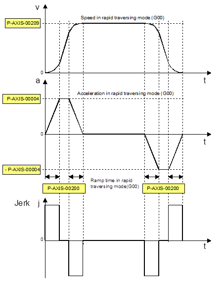
Parameterisation for rapid traverse (G00)
The jerk-limited acceleration profile with steeper acceleration ramps can be defined for rapid traverse motions (G00). All acceleration ramps (segments: I, III, V and VII) are parameterised at maximum acceleration P-AXIS-00004 and maximum ramp time P-AXIS-00200 (see figure below).
Parameterisation for feedhold
Acceleration ramps (segments I, III, V and VII) are parameterised at maximum acceleration P-AXIS-00053 and maximum ramp time P-AXIS-00081 for rapid deceleration on feed stop (feedhold).
The influence of the channel parameter P-CHAN-00097 must be considered.