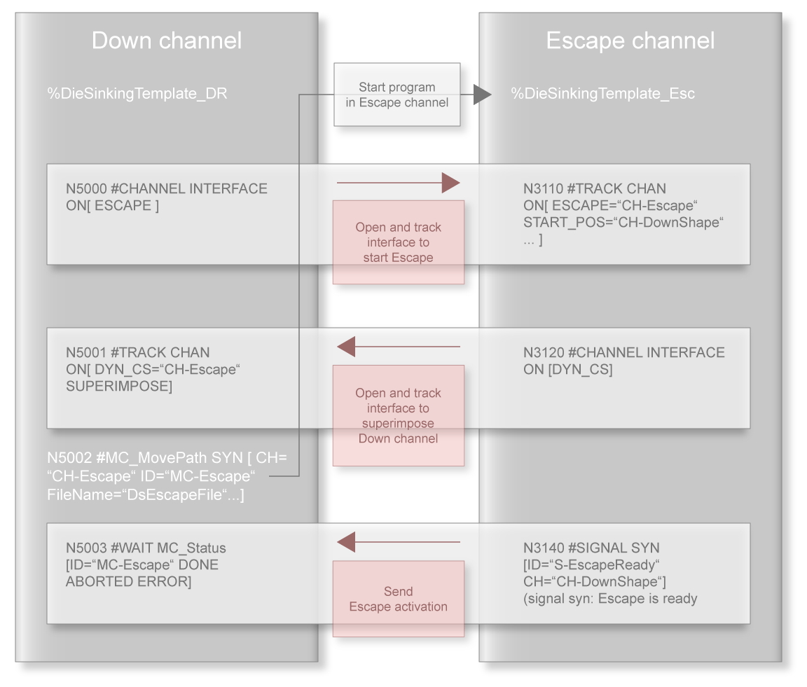
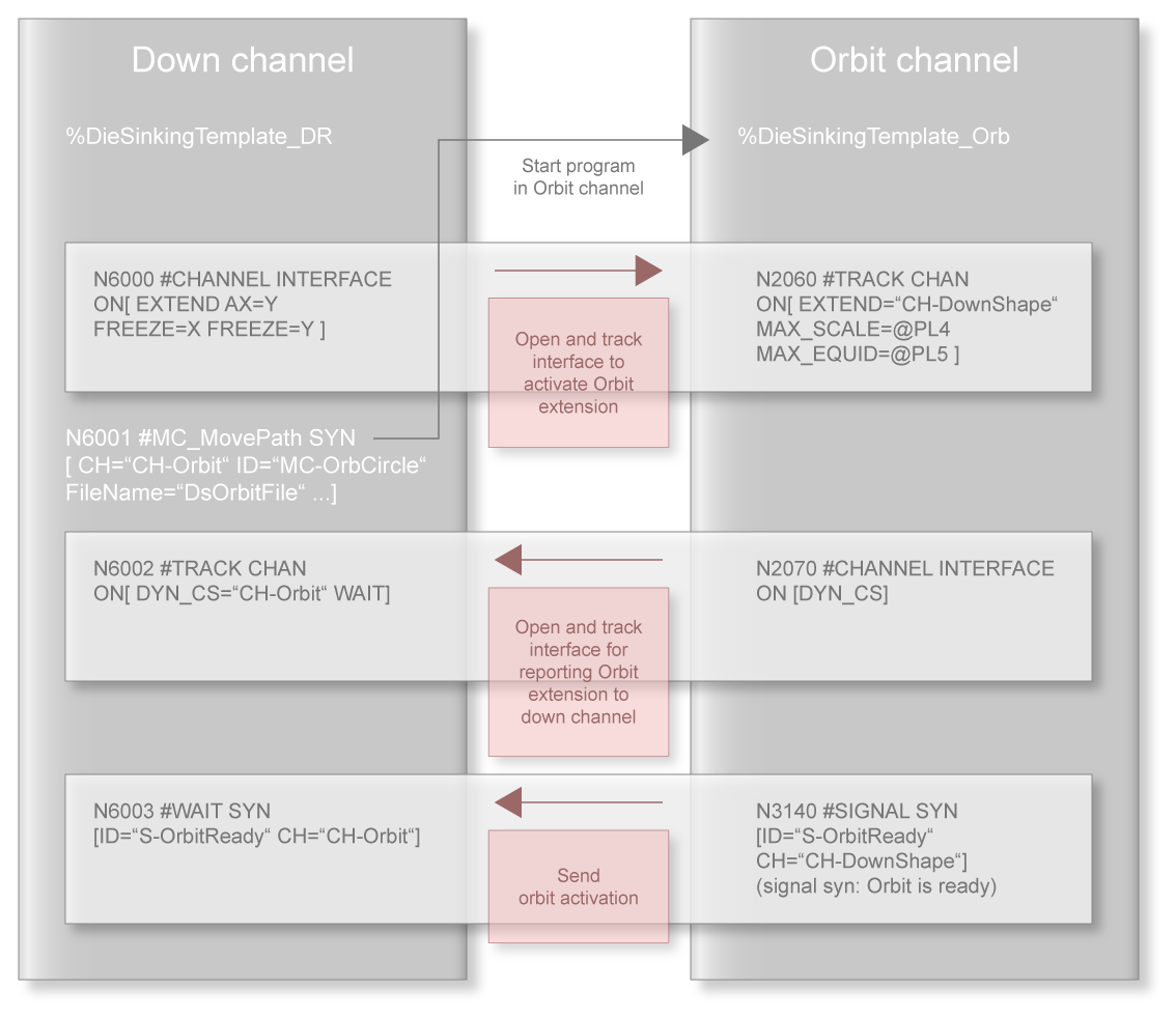
General channel initialisation/coupling
The individual erosion phases of positioning, erosion on the path, orbiting and end of machining are implicitly defined by channel couplings (see Down channel). The figures below give an overview of how these channel couplings are implemented in each off the channels in the programming.
It should be noted that the interfaces are always unidirectional, i.e. a channel can write data to an interface that it opens and the partner channel can read data from it. However, in order to receive data from the partner channel, the partner channel must also open an interface. Therefore, every
#CHANNEL INTERFACE ON ; open interface to write
NC command in transmitting channel is followed by a
#TRACK CHAN ON ; open interface to read
NC command in receiving channel.
Notice

The end point of the erosion phase on the path must have the PCS position 0 for the X and Y axes.
Notice
The orbit channel can only be decoupled if the down channel is in the centre (radius = 0). The down channel may not be superimposed on the escape channel at this time.
Notice
The escape channel can only be decoupled if no escape motion is active at this time. To prevent decoupling of the escape channel while an escape motion is active, use the #CHANNEL INTERFACE OFF [ESCAPE WAIT] command.]
The arrows in the figures below show the direction of information flow.
In summary, this results in the basic overall structure for a standard die sinking program as shown in the figure below.
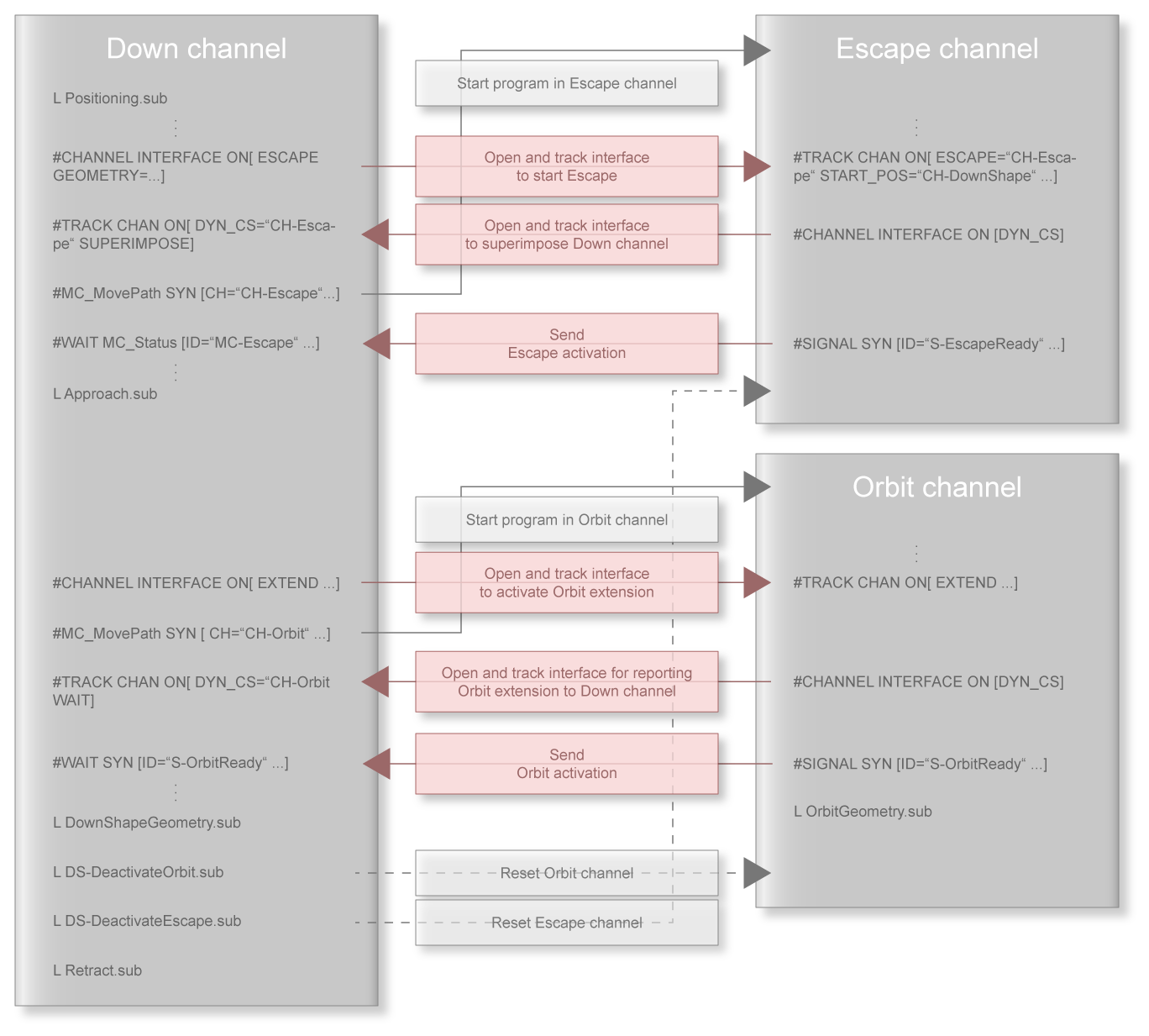
The next section presents NC program templates for the down channel. First, the overall program is discussed before the programs are presented for coupling the escape and orbit channels by the down channel ( figures / left half of the figure).
This is followed by a presentation of the general program structure including the program sequences for coupling channels from both the orbit channel and the escape channel.