Premature change of generator settings
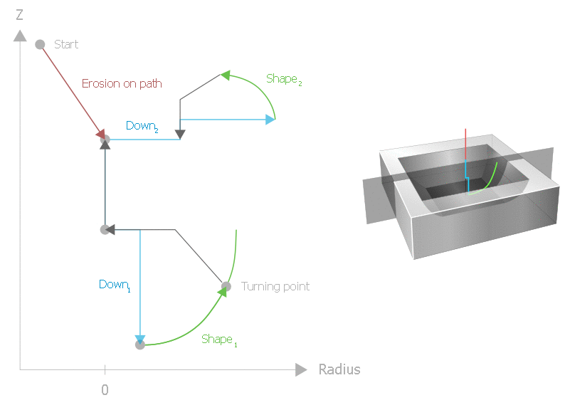
If the surface finish of the current machining stage is found to be of sufficient quality, you can change directly to the next machining stage to shorten machining time. Machining should then be aborted at the current point, the electrode removed from the cavity and machining continued at another point in the program, for example with a different orbit geometry and escape strategy.

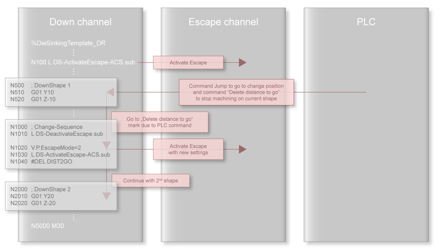
The “Delete distance to go” function is used to change generator settings prematurely. When jump labels are used, it removes all geometry elements and other NC commands until the selected jump label is reached. The NC program must meet various requirements to enable changes to be made to generator settings using this function.
- The radius of the down channel must be 0 if the orbit channel is to be deactivated and reactivated.
- Restrictions in the “Delete distance to go” function must be considered, for example not all commands can be skipped. Here is a selection of die-sinking commands that cannot be skipped:
- #CS ON
- #TRAFO ON
- #CHANNEL INIT
- #TRACK CHAN OFF; the “Delete distance to go” command is aborted with #CHANNEL INIT and #TRACK CHAN OFF and the following blocks are executed starting from the current position.
- There is a further restriction of the “Delete distance to go” function in connection with circular elements. Circular elements (G02 / G03) are often programmed relative to the end point of the previous block (G162). If the next motion block after the jump label is a circular element, the current position must be the same as if the program had been executed without ‘Delete distance to go’. If circular elements are programmed using absolute end points (G161), the current position must be on the circular arc.
One way of avoiding this problem is to program a linear motion block at the starting point of the circular element before the circular element (that follows directly after the selected jump label). This would have distance 0 if executed without ‘Delete distance to go’.
The program sequence for changing generator settings is normally as follows:
- Execute a flushing process at a possible change position (e.g. end point of erosion on the path or radius = 0). This is where generator settings are changed.
- Deactivate the escape channel, if required.
- Deactivate the orbit channel, if required.
- Reorient the down channel, if required.
- Reactivate the orbit channel in its new orientation.
- Reactivate the escape channel.
- Continue the second geometry.
One way to set the generator change point to the end point of erosion on the path is to program an M01 function at the end of the path geometry. Before a flushing process of sufficient length is commanded, this optional stop in the escape channel must be activated using the corresponding control unit.
A second option for reaching a selected generator change point is to command a flushing process where the required distance and floating distance are identical. A flushing process can then be commanded to end immediately when the selected distance is reached.
By inserting conditions at the start of the second geometry that compare the current position with a specified value, the second geometry can contain different motion sequences depending on whether a generator change has taken place. A programming example for this application is shown in Premature change of generator settings.
