Tolerance monitoring
Tolerance monitoring provides a simple and reliable method for handling filters.
The automatic monitoring of axis errors only intervenes if axis errors become excessive when axis filters are used.
The user must specify the maximum permitted tolerance in the NC program.
To depict the operating principle of tolerance monitoring, the figure below presents a comparison of contours of a motion “without filter” (blue curve top right), ‘with filter’ (red curve’ and ‘with filter and tolerance monitoring’ (green curve in a corner of the program. The program of the example used here is a programming example taken from the Section Programming.
An moving average filter with an order of 40 is used as filter. The specified tolerance is 0.001mm.

Blue | without filter |
Red | with filter |
Green | with filter and tolerance monitoring |
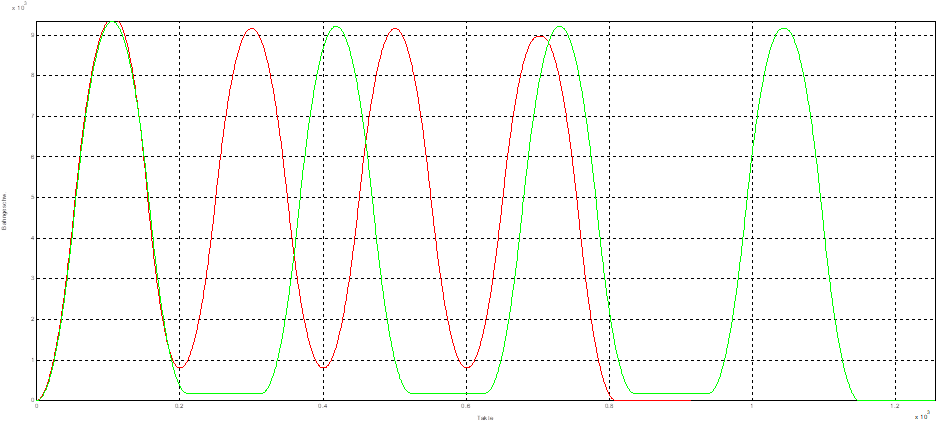
Functionally, an intervention by tolerance monitoring ensures that the path velocity is only reduced at the relevant points in the program (Operating principle) Reducing path velocity is based here on the axis with the largest anticipated axis error in the particular situation. The velocity is reduced until the axis error no long exceeds the tolerance limit. Moreover, it should also be ensured that the size of any reduction is only as small as required to limit the machining velocity of the program as little as possible. To depict the function of tolerance monitoring, the figure below shows the path velocity with (green curve) and without (red curve) tolerance monitoring. The ramps with reduced velocities caused by tolerance monitoring (green curve) are easily visible at the program corners.
The tolerance monitoring of FIR filters is intended to obtain the best possible balance between machining velocity and accuracy while at the same time minimising the excitation of the machine to vibrate.
Notice

Deviation or axis error and machining velocity have a uniform behaviour. Less deviation = lower machining velocity; more deviation = higher machining velocity.
As a result, tolerance monitoring generally entails a longer machining time.
Notice
Tolerance monitoring monitors the axis errors of all axes and not the contour deviation.
Notice
Tolerance monitoring always monitors the current axis setpoint curve. This means that any path adaptations, for example an activated contouring mode, are also included in the filtered setpoint curves. The specified tolerance then always refers to the already modified setpoint curve, i.e. it is added.
Maximum contour deviation is dependent on the machine kinematics. Since tolerance monitoring only monitors the maximum error per axis, the contour error may vary. This results from interaction between the individual axes. As an example, this can be determined as follows for simple kinematics:
- Cartesian axes in 2D motion:

- Cartesian axes in 3D motion:
