Step-shaped acceleration profile
Description and properties
Therefore, select this profile to obtain the shortest possible positioning times.
This profile is used very frequently and has a stepped acceleration profile. This results in dynamic motion segments for individual axes which are controlled at a linear velocity rise/drop over time. At the start of the block, acceleration takes place up to the programmed feed rate, followed by deceleration at the maximum permissible acceleration towards the end of the block.
Returns occur during axis acceleration ramp-up and deceleration. This is due to the stepped acceleration profile. This response can have a negative impact on machine constructions that are subject to critical vibrations. However, the great advantage lies in the optimum distance/time response, i.e. the time needed for a path motion segment is the shortest compared to other acceleration profiles.
Parameterisation
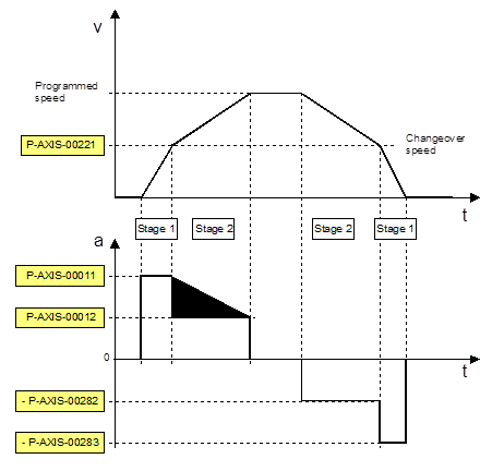
During both start-up and deceleration, the acceleration profiles each consist of 2 steps which can be parameterised with 2 different acceleration values.
- Step 1 is accelerated and decelerated at the acceleration value of P-AXIS-00011.
- Step 2 is accelerated and decelerated at the acceleration value of P-AXIS-00012.
The parameter P-AXIS-00221 sets the changeover velocity from one acceleration value to the other. The linear velocity profile and the stepped acceleration profile of a typical parameterisation variant are depicted in the above figure “Parameters of the linear velocity profile”. Of course, another possible setting is where acceleration value 1 is less than acceleration value 2.
Parameterisation for rapid traverse (G00)
Another parameter set is available for dynamic motion segments with active rapid traverse (G00).
- The acceleration value P-AXIS-00005 is active in step 1.
- The acceleration value P-AXIS-00006 is active in step 2.
The changeover velocity can be defined by the parameter P-AXIS-00211 in rapid traverse.
Parameterisation for feedhold
The acceleration value for feedhold to decelerate the axis to standstill is set by the parameter P-AXIS-00024.
The influence of channel parameter P-CHAN-00097 must be taken into account.