PLCopen programming
A list of PLCopen functions is contained in the various PLCopen descriptions.
The scope of the Motion Control Platform (MCP) provides a number of function blocks (FB) for motion tasks. These FBs act on a single axis and are operated via the SPS. Each axis in the system is configured in the system as a so-called Single Axis Interpolator (SAI).
Alternatively these axes also can be addressed by the NC program because an SAI is always configured in the system as a conventional spindle. Special NC commands are therefore provided for the following FBs. These commands permit PLCopen-conforming programming in NC syntax.
MC_Home | Homing |
MC_MoveAbsolute | Axis motion to an absolute position |
MC_MoveAdditive | Relative axis motion to the commanded position |
MC_MoveRelative | Relative axis motion to the current position |
MC_MoveSuperImposed | Relative axis motion to a motion already active |
MC_MoveVelocity | Endless axis motion at the specified velocity |
MC_Stop | Stop an axis motion |
MC_GearIn | Gear coupling with a gear ratio |
MC_GearOut | Release a gear coupling |
MC_Phasing | Phase offset of couplings |
MC_TouchProbe | Measurement of axis positions |
The topology below displays the basic arrangement of SAI (spindle) axes within the overall system:
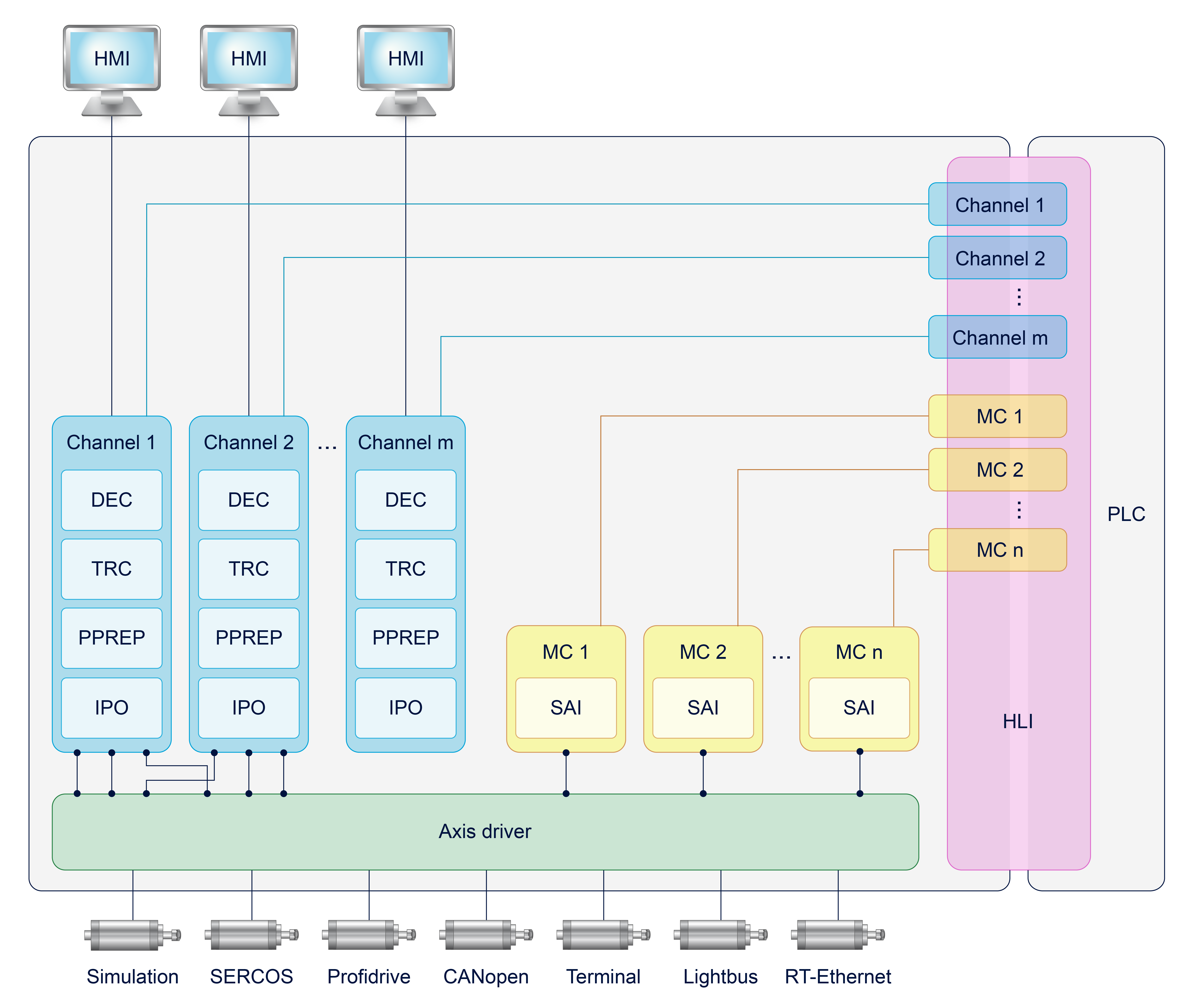
An SAI axis is addressed in the NC program in spindle-specific programming syntax. It must therefore be configured in the NC channel by its address letters and other data analogous to the configuration of a spindle in the channel parameter list. The most important settings in the channel parameter list are:
- spdl_anzahl (P-CHAN-00082) – Total number of (SAI) spindles
- bezeichnung (P-CHAN-00007) – Name of the (SAI) spindle
- log_achs_nr (P-CHAN-00036) – Logical axis number of the (SAI) spindle
For more information, see the documentation [1] Section: Configuring spindles- and the Section Parameterising spindles.
The PLCopen functions
- MC_MoveSuperImposed
- MC_GearIn
- MC_GearOut
- MC_Phasing
- MC_TouchProbe
require additional specific SAI characteristics of the (spindle) axis which are configured in the axis parameters. The required settings are contained in the documentation [2]-Section: SAI settings.
Each NC command of the corresponding FB is presented below. The syntax of these NC commands and the units of the programmed values are based on the corresponding input pins (VAR_INPUT) of the assigned FBs.
|
<spindle_name>[ <FB_name> <input_pin1> <input_pin2> <input_pin n...> { \ } ]] |
The axis name at the start of the NC command addresses the (SAI) spindle axis which is addressed by the NC channel.
The description of the input pins and the units and value ranges are also contained in the documentation [9].
Notice

All input pin values are programmed in metric units. In initial state the values must be specified in the specified internal units (e.g. 0.1 µm). The parameter P-CHAN-00182 can be changed to specify values in default units (e.g. mm).
The input pin "Execute" is always assigned implicitly by programming the NC command. This is why no specific keyword is provided for this pin.
The line separator '\' can be used within the [...] brackets to obtain a clear programming of the command over multiple lines.
The keywords "Id" and "WaitSyn" for job synchronisation in the NC program have no corresponding PINs in the PLC. The two keywords are available as of CNC Build V3.01.3100.01
By default PLCopen functions are executed irrespective of other NC program processing. There is no synchronisation between PLCopen single-axis jobs and path motion.
However, wait conditions can be defined to synchronise PLCopen functions with the program run. There are two options here:
1) Synchronisation at block end:
Defining the “WaitSyn” keyword causes the CNC to wait for the completion of the PLCopen job before continuing to the next NC block. If several PLCopen jobs are programmed in the NC line, continuation only takes place when all the jobs specified for the “WaitSyn” keyword are completed.
Syntax |
<spindle_name>[ <FB_name> [WaitSyn] <input_pin1> <input_pin n...> { \ } ] |
Programing Example

N10 G01 X100 F10000
N20 S[MC_MoveAbsolute WAIT_SYN POSITION=900000 …]
;Continue to block N30 when spindle S reaches ;position 90°
N30 G01 X200 F100
2) Late synchronisation:
The “Id” keyword can be used to assign a job ID to a PLCopen job. The #WAIT MC_STATUS SYN [ID<JobNo>] command can wait for the end of the PLCopen job at a later time.
Syntax |
<spindle_name>[ <FB_name> [Id=..>] <input_pin2> <input_pin n...> { \ } ] |
#WAIT MC_STATUS SYN [ID=.. { ID=.. } ] |
If several PLCopen jobs with identical job numbers are started, the job number is assigned to the last PLCopen function commanded. It is then possible that the job last started may be subject to later synchronisation at job end.
Programing Example
N10 G01 X100 F10000
N20 S[MC_MoveAbsolute Id100 POSITION=900000 …]
N30 G01 X200
N40 S2[MC_MoveVelocity Id200 Velocity=10000 …}
N50 G01 X300
N60 #WAIT MC_STATUS SYN [ID100 ID200]
; Continue to block N70 takes place when spindle S
; reaches position 90° and spindle S2 reaches the speed 10°/s
N70 G0 X0