Channel parameter
Further entries which are made in the channel parameters are required for programming spindles in the NC program [1].
In this case, each spindle to be addressed by this channel must be declared. For this purpose, a string (axis name) and the corresponding logical axis number are defined for each spindle. The axis names of the spindle can be freely selected but they must always start with "S" (e.g. S, S_MAIN, S1, SPINDEL_1).
In addition, the synchronisation modes must be defined spindle-specific for the spindle M functions (M3, M4, M5 and M19) and for the S word. The appropriate meaning of M3, M4, M5 and M19 must then be switched (P-CHAN-00098).
Notice

The synchronisation method of the S function has no effect if a spindle M function is programmed in the NC block. Synchronisation only takes place based on the settings for the spindle M function. The following priorities apply:
M19 > M3/M4/M5 > S
If the spindles are to be considered in the "Production time calculation” simulation mode, the data required for this can also be parameterised spindle-specific.
To ensure that this remains compatible with previous programming, one spindle must be declared as the main spindle (P-CHAN-00051, P-CHAN-00053). The main spindle can then be programmed together with specific standard functionalities (e.g. tapping and gear changing etc.) in the conventional DIN syntax. Even if there is only one spindle in the system, it must be configured as the main spindle.
The optional gear changing function for the main spindle (P-CHAN-00052) is also enabled by setting a flag.
The default configuration defined in the channel parameters [1] is provided after controller start-up.
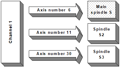
Example 1:
Configuration of a 1-channel system with 3 spindles. The spindle with axis number 6 is to be the main spindle. Gear change for this spindle is deactivated.
Channel parameter list [1]:
:
spdl_anzahl 3
:
main_spindle_ax_nr 6 -> -> ->-
main_spindle_name S |
main_spindle_gear_change 0 |
# |
spindel[0].bezeichnung S1 |
spindel[0].log_achs_nr 6 -< -< -<-
spindel[0].s_synch 0x00000001
spindel[0].m3_synch 0x00000002
spindel[0].m4_synch 0x00000004
spindel[0].m5_synch 0x00000008
spindel[0].m19_synch 0x00000001
spindel[1].bezeichnung S2
spindel[1].log_achs_nr 11
spindel[1].s_synch 0x00000001
spindel[1].m3_synch 0x00000002
spindel[1].m4_synch 0x00000004
spindel[1].m5_synch 0x00000008
spindel[1].m19_synch 0x00000001
spindel[2].bezeichnung S3
spindel[2].log_achs_nr 30
spindel[2].s_synch 0x00000001
spindel[2].m3_synch 0x00000002
spindel[2].m4_synch 0x00000004
spindel[2].m5_synch 0x00000008
spindel[2].m19_synch 0x00000001
:
After start-up, the spindle with the logical axis number 6 is the main spindle. It is addressed via the spindle name "S” and can be programmed in conventional DIN syntax or in spindle-specific syntax. Spindles "S2” and "S3” can only be programmed in spindle-specific syntax.
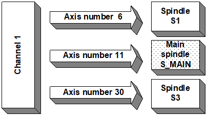
Example 2:
Configuration of a 1-channel system with 3 spindles. The spindle with axis number 11 is to be the main spindle. Gear changing for this spindle is deactivated.
Channel parameter list [1]:
:
spdl_anzahl 3
:
main_spindle_ax_nr 11 -> -> -> ->
main_spindle_name S_MAIN |
main_spindle_gear_change 0 |
# |
spindel[0].bezeichnung S1 |
spindel[0].log_achs_nr 6 |
spindel[0].s_synch 0x00000001 |
spindel[0].m3_synch 0x00000002 |
spindel[0].m4_synch 0x00000004 |
spindel[0].m5_synch 0x00000008 |
spindel[0].m19_synch 0x00000001 |
spindel[1].bezeichnung S2 |
spindel[1].log_achs_nr 11 -< -< -< -<
spindel[1].s_synch 0x00000001
spindel[1].m3_synch 0x00000002
spindel[1].m4_synch 0x00000004
spindel[1].m5_synch 0x00000008
spindel[1].m19_synch 0x00000001
spindel[2].bezeichnung S3
spindel[2].log_achs_nr 30
spindel[2].s_synch 0x00000001
spindel[2].m3_synch 0x00000002
spindel[2].m4_synch 0x00000004
spindel[2].m5_synch 0x00000008
spindel[2].m19_synch 0x00000001
:
After start-up, the spindle with the logical axis number 11 is the main spindle. It is addressed by the spindle name "S_MAIN” and can be programmed in conventional DIN syntax or in spindle-specific syntax. Spindles "S1” and "S3” can only be programmed in spindle-specific syntax.
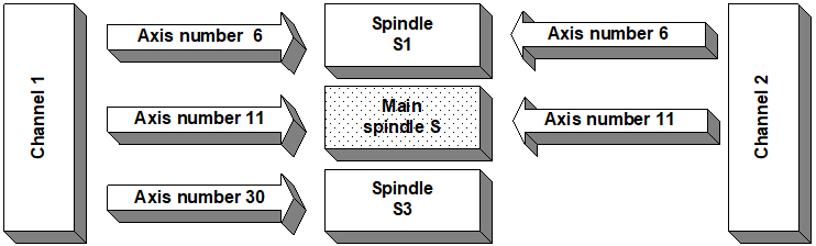
Example 3:
Configuration of a 2-channel system with a total of 3 spindles:
Channel 1: 3 spindles. Spindle with the axis number 11 is to be the main spindle.
Channel parameter list [1]:
:
spdl_anzahl 3
:
main_spindle_ax_nr 11 -> -> -> ->
main_spindle_name S |
main_spindle_gear_change 0 |
# |
spindel[0].bezeichnung S1 |
spindel[0].log_achs_nr 6 |
spindel[0].s_synch 0x00000001 |
spindel[0].m3_synch 0x00000002 |
spindel[0].m4_synch 0x00000004 |
spindel[0].m5_synch 0x00000008 |
spindel[0].m19_synch 0x00000001 |
spindel[1].bezeichnung S2 |
spindel[1].log_achs_nr 11 -< -< -< -<
spindel[1].s_synch 0x00000001
spindel[1].m3_synch 0x00000002
spindel[1].m4_synch 0x00000004
spindel[1].m5_synch 0x00000008
spindel[1].m19_synch 0x00000001
spindel[2].bezeichnung S3
spindel[2].log_achs_nr 30
spindel[2].s_synch 0x00000001
spindel[2].m3_synch 0x00000002
spindel[2].m4_synch 0x00000004
spindel[2].m5_synch 0x00000008
spindel[2].m19_synch 0x00000001
:
Channel 2: 2 spindles. Spindle with the axis number 11 is to be the main spindle.
Channel parameter list [1]:
:
spdl_anzahl 2
:
main_spindle_ax_nr 11 -> -> ->-
main_spindle_name S |
main_spindle_gear_change 0 |
# |
spindel[0].bezeichnung S1 |
spindel[0].log_achs_nr 6 -< -< -<-
spindel[0].s_synch 0x00000001
spindel[0].m3_synch 0x00000002
spindel[0].m4_synch 0x00000004
spindel[0].m5_synch 0x00000008
spindel[0].m19_synch 0x00000001
spindel[1].bezeichnung S2
spindel[1].log_achs_nr 11
spindel[1].s_synch 0x00000001
spindel[1].m3_synch 0x00000002
spindel[1].m4_synch 0x00000004
spindel[1].m5_synch 0x00000008
spindel[1].m19_synch 0x00000001
:
After start-up, the spindle with the logical axis number 11 can be addressed as the main spindle by spindle name "S” for both channels. It can be programmed in conventional DIN syntax or in spindle-specific syntax. Spindle “S1” can also be programmed from both channels in spindle-specific syntax. Spindle “S3” is only available in channel 1. This spindle is not known in channel 2.