Extended programming of axis couplings (“SOFT-GANTRY“) (#SET AX LINK, #AX LINK)
Release Note
The availability of this function depends on the configuration and on the version scope.
Path axes can also be used as so-called gantry axes. Contrary to normal synchronous mode, additional position deviation monitoring mechanisms are active and specific error reactions apply. Due to the machine structure, the axes are permanently linked to each other in mechanical (and static) gantry operation and defined by the machine configuration. After controller start-up it not possible to make a dynamic change in the gantry coupling (see figure below).
In addition to path axes, spindles can also be run in synchronous mode. A detailed description is contained in section Spindle synchronous mode.
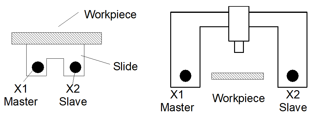
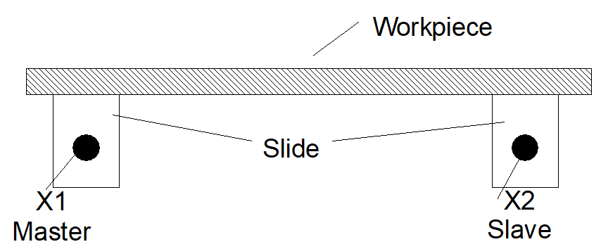
Machines that do not permit any mechanical gantry operation because of their basic structure, e.g. milling machines with two independent slides, can be operated in gantry mode by programming. For example, this is necessary when slides must be linked to one another for clamping and machining large workpieces (see Figure below)
The #SET AX LINK and #AX LINK commands described in section Programming axis couplings are available in an extended syntax for this purpose:
Syntax: |
#SET AX LINK [ <coupling_group>, [ <slave>=<master>,G [,<limit_1>, limit_2>] ] {, [ <slave>=<master>,G [,<limit_1>, limit_2>] ] } ] |
or alternatively
#AX LINK [NBR] [ <coupling_group>, [ <slave>=<master>,G [,<limit_1>, limit_2>] ] {, [ <slave>=<master>,G [,<limit_1>, limit_2>] ] } ] |
<coupling_group> | Number of the coupling group (1) |
<Slave> | Designation or logical axis number of the slave axis of coupling pair i (2) |
<master> | Designation or logical axis number of the master axis of coupling pair i (2) |
NBR | Evaluation can be changed from logical axes names to axes numbers with the logic switch NBR. The axis couplings must then be defined with logical axis numbers. The axes need not be present in NC channel. Their availability in NC channel is checked only at activation of the coupling group! |
G | Keyword for "gantry coupling" |
(1) 1 ... [Max. number of coupling groups–1], see [6] -2.11
(2) Max. number of coupling pairs, see [6] -2.12
When gantry coupling is used, the following values serve to monitor in two stages the permissible position difference of the gantry axes. Specified in [mm]. Positive real number:
<limit_1> | First monitoring limit in [mm, inch]. If this limit is exceeded, the motion is aborted and the controller assumes the error state. In the default case, the position difference is cancelled during RESET. Depending on the specific application, deviating motion can still be realised. |
<limit_2> | Second monitoring limit in [mm, inch]. An error that cannot be RESET is output if this limit is exceeded. The controller must be switched off and the position difference must be eliminated manually. |
Notice

If the monitoring limits are not programmed, the defaults apply from the axis parameter data records P-AXIS-00072 and P-AXIS-00071 of the slave axis.
Additions to general handling and mode of operation
- Gantry coupling takes place at precisely the positions where the axes are at the time when coupling is selected. There is no need to specify an offset in the NC command because the offset is calculated internally in the position controller via the nominal positions.
- The dynamic data of the slave axis is taken into account in the contouring motion.
- For safety reasons, a coupling which is still active on RESET or at program end is implicitly restored the next time the program is started. This reaction is parameterisable (P-CHAN-00104, P-CHAN-00105).
Programing Example

Extended programming of axis couplings (SOFT-GANTRY)
N10 #SET AX LINK[1, [Y2=Y1,G,0.01,0.25]] | Gantry coupling of Y1 as master axis and Y2 as slave axis. First limit is 10 µm, second limit is 250 µm. |
N20 #SET AX LINK[2, [Y2=Y1,G]] | Gantry coupling of Y1 (master) and Y2 (slave). The monitoring limits of the axis parameter data block of the Y2 axis apply. |
N30 #SET AX LINK [3,[Y2=Y1]] | Standard coupling of Y2 with Y1. No gantry operation. |
or alternatively |
|
N10 #AX LINK[1, [Y2=Y1,G,0.01,0.25]] | |
N20 #AX LINK NBR[2, [8=2,G]] | Gantry coupling via log. axis numbers |
The parallel machining of workpieces with a symmetrical or scaled contour can also be programmed by means of an extended syntax of the #SET AX LINK and #AX LINK commands. Position differences are not monitored in these modes (mirroring or scaling).
Syntax: |
#SET AX LINK [ <coupling_group>, [ <slave>=<master>,<nominator>, <denominator> ] {, [ <slave>=<master>,<hominator>, <denominator ] } ] |
or alternatively
#SET AX LINK [NBR] [ <coupling_group>, [ <slave>=<master>,<nominator>, <denominator> ] {, [ <slave>=<master>,<hominator>, <denominator ] } ] |
<coupling_group> | Number of the coupling group (1) |
<Slave> | Designation or logical axis number of the slave axis of coupling pair i (2) |
<master> | Designation or logical axis number of the master axis of coupling pair i (2) |
NBR | Evaluation can be changed from logical axes names to axes numbers with the logic switch NBR. The axis couplings must then be defined with logical axis numbers. The axes need not be present in NC channel. Their availability in NC channel is checked only at activation of the coupling group! |
<numerator>, <denominator> | Integers. Their purpose is to calculate a coupling factor between the master and slave axes. The following applies to the resulting coupling factor: -1 : mirror coupling 1 : standard coupling; equivalent to the previous syntax 0 : output of an error message |
Attention

Factors that result in pure scaling (factor ≠ 1) or in scaling with simultaneous mirroring (factor ≠ -1) are currently not permitted. A warning is output and the coupling is handled as a standard coupling. This means that only coupling factors 1 and –1 are permissible (see examples).
(1) 1 ... [Max. number of coupling groups–1], see [6] -2.11
(2) Max. number of coupling pairs, see [6] -2.12
Programing Example
N10 #SET AX LINK[1, [Y2 = Y1,1,-1]] | Mirroring coupling (factor -1) |
N20 #SET AX LINK[1, [Y2 = Y1,-1,1]] | Mirroring coupling (factor -1) |
N30 #SET AX LINK[1, [Y2 = Y1,-2,2]] | Mirroring coupling (factor -1) |
N40 #SET AX LINK[1, [Y2 = Y1,1,1]] | Standard coupling |
N50 #SET AX LINK[1, [Y2 = Y1,2,2]] | Standard coupling |
N60 #SET AX LINK[1, [Y2 = Y1,0,1]] | Error message, program is aborted |
N70 #SET AX LINK[1, [Y2 = Y1,1,0]] | Error message, program is aborted |
N80 #SET AX LINK[1, [Y2 = Y1,1,2]] | Warning (factor 0.5), standard cpl. |
N90 #SET AX LINK[1, [Y2 = Y1,2,3]] | Warning (Factor 0.666), Standard cpl. |
N100 #SET AX LINK[1, [Y2 = Y1,3,2]] | Warning (factor 1.5), standard cpl. |
N110 #SET AX LINK[1, [Y2 = Y1,-1,2]] | Warning (factor -0.5), standard cpl. |
N120 #SET AX LINK[1, [Y2 = Y1,-3,2]] | Warning (factor -1.5), standard cpl. |
or alternatively | |
N40 #AX LINK[1, [Y2 = Y1,1,1]] | Standard coupling |
N50 #AX LINK NBR[1, [8 = 2,2,2]] | Standard coupling via log. axis numbers |