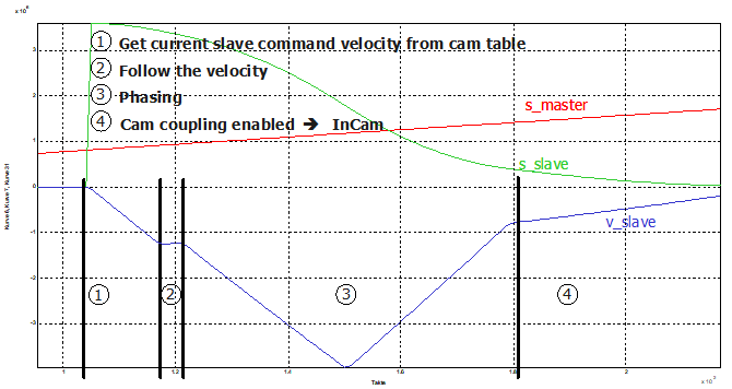
Influence of axis parameters on the coupling process
What is referred to as a real amplitude ramp-in takes place both with a running master axis and at standstill.
With a running master axis this equates to the following mechanical analogy: Engaging a cam on a running master shaft. The coupling has slip until the cam to be driven along with it is at the right speed. The cam is then brought to the right position.)

The following parameters of the axis MDS influence this behaviour:
Axis parameters | Parameter-ID | Description |
cam_gear.v_diff_percent | Velocity tolerance in phase 2. | |
cam_gear.time_in_window | Min. duration of phase 2. | |
cam_gear.time_out_in_window | Max. duration of phase 2. |
Synchronisation of the speed is jerk-limited. The jerk value must be set in the axis MDS in the parameter cam_gear.j_vel_sync (P-AXIS-00377).
Values that correspond to a minimum ramp time of TA(cycle time of the IPO, e.g. 2 ms) and a maximum ramp time of 100s make sense as the jerk. The limit transition to non-jerk-limited speed realisation lies at the minimum ramp time of TA.
In the case of a value of 0, the maximum ramp time from the axis MDS is used to determine the jerk.
Notice

If the slave axis is a linear axis, make sure that the slave axis does not cross the software limit switch when the position is synchronised.
Notice

In the coupled state, the coupling is "holy", i.e. axis-specific feed hold, axis-specific override CANNOT act on the cam slave because this would be contradictory to the coupling specification.
The behaviour at emergency stop is implemented as follows: The MCE is only signalled about an emergency stop situation via the drive interface. In the event of an emergency stop, the coupling is released and decelerated at the current limit which is entered in the axis MDS parameter getriebe[0].lslope_profil.a_grenz_stufe_1 (P-AXIS-00005). This default behaviour in the event of an emergency stop can be deactivated by using the parameter cam_gear.keep_coupling_on_lr_error (P-AXIS-00308). Then coupling is ensured even in the event of Emergency Stop as long as the drive still follows the setpoints.
In conjunction with the safety function which triggers an unconditional feedhold [HLI//Watchdog with effect on feedhold] in the event of a watchdog trigger failure, the MC response to a watchdog trigger failure is to cancel the axis coupling and decelerate the axes at the current brake entered in the associated axis MDS parameter getriebe[0].lslope_profil.a_grenz_stufe_1 (P-AXIS-00005).
This default behaviour in the event of a watchdog trigger failure by the PLC can be deactivated by the parameter cam_gear.keep_coupling_on_fe_drop (P-AXIS-00309). This safeguards the coupling even in the event of a watchdog trigger failure.
Automatic phasing is also jerk-limited after velocity synchronisation is reached. Consequently, the following parameters must be set in the slave:
- cam_gear.v_phasing (P-AXIS-00305) Velocity of the superimposed motion for phasing
- cam_gear.a_phasing (P-AXIS-00306) Acceleration of the superimposed motion for phasing
- cam_gear.d_phasing (P-AXIS-00307) Deceleration of the superimposed motion for phasing
- cam_gear.j_phasing (P-AXIS-00376) Jerk of the superimposed motion for phasing