Superimposing geometry and escape motions
Control by the PLC
The PLC can fully monitor and control the synchronisation of the down channel and escape channels, i.e. the PLC can achieve the required response using the appropriate interfaces.
- The PLC is the master.
- The down channel and escape channel are slaves.
In standard machining operations, the escape channel only superimposes the down channel until the down channel is at standstill. This condition is monitored by the CNC while erosion takes place on the path and if ignored, it results in an error message and a machining process abort.
During the orbiting phase, it is possible to simultaneously move and superimpose the two channels. The escape path is adapted online to the changed start position of the down channel. Superimposition results in a type of looping of the escape and geometry motions.
However, superimposition may lead to dynamic problems. In this machining operation, the electrode can be “pushed” over corners without a motion stop at the bending point. In the worst case, this can result in additional axis acceleration.
With
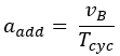
 : path velocity in down channel
 : Cycle time
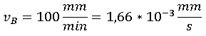 : standard value for path velocity.
Regardless of the programmed feed rate or the external commanded velocity specified by the PLC, the maximum path velocity in the down channel can be limited to this standard value by the command #VECTOR LIMIT ON [VEL=100].

Sliding end of the escape motion
When the electrode returns to the contour after withdrawing through the escape channel, the simultaneous commanded velocity specified by the PLC on the down and orbit channels allows a soft return to the workpiece as of a specified distance.
This distance defines a circular area about the starting point of the down channel and can be defined by the dist_prog_start control unit [HLI, section: Status information of a channel] of the escape channel.