Description
EDM mainly differs from other forms of machining, such as milling, due to its method of material removal. Instead of mechanical removal, the electrode and the workpiece are electrically charged during erosion and the material is then melted and vaporised by a spark. The gap between the workpiece and the electrode must be continuously controlled during the process in order to achieve optimum machining results.
In die sinking, the workpiece is eroded by an electrode that has the negative shape to produce the workpiece. The workpiece is usually immersed in a tank containing a dielectric. In order to evacuate the removed material, the electrode is quickly retracted from the workpiece and the material is flushed out. This document describes how to set up a die sinking machine using the ISG kernel and what functions the ISG kernel offers for die sinking.
The figure below shows an overview of the individual components involved in motion control in the EDM process:
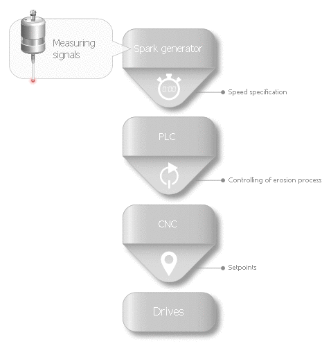
The spark generator is the component that provides the specified velocities to control the gap based on the current values measured on the workpiece. The PLC uses this specified setting depending on the current erosion mode to transfer the necessary data to the CNC to guide the electrode motion. This generates the setpoints for the drives while maintaining maximum dynamics for optimum motion control to achieve optimum machining results.
Phases of the EDM process
The CNC provides 4 processing phases for the EDM process:
- Positioning when the EDM process is not active
- Erosion on the path (optional)
- Erosion with orbiting (optional)
- Electrode escape after the EDM process
When positioning, the electrode is moved to a position above the starting point for machining.
It can then be decided how the workpiece is to be machined. A distinction is made between erosion on the path, erosion with orbiting or erosion on the path followed by erosion with orbiting.
The machining processes differ in the way the electrode is guided. In erosion on the path, the electrode moves forwards and backwards along a programmed path.
In erosion with orbiting, the motion of the electrode is produced from two asynchronous or synchronised 2D geometries. The escape motion away from the current electrode point is calculated based on an escape strategy.
After EDM machining, the electrode can be retracted from the workpiece.

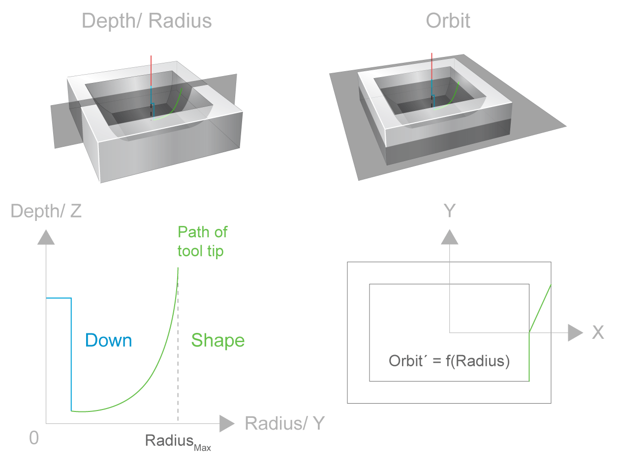
Electrode motion for orbiting
Guiding the electrode when orbiting is divided into 2 processes:
- Down to the RZ plane
- Orbit motion in the X-Y plane
These processes can be completely asynchronous or partially synchronised depending on the type of EDM used.
A third process is activated for the escape motion of the electrode. It assumes the spark generator-controlled escape strategy and the flushing process in real time.
CNC architecture for die sinking
In order to fulfil the requirements of the EDM process, three NC channels are used in the CNC control system and together they control the axes of the EDM machine.
The three channels are shown in the figure below: In this document, they are referred to as follows:
- Down channel
- Orbit channel
- Escape channel
Each channel is always assigned its own NC program and has its own status and position display. The down channel is the main channel controlling the orbit and escape channels and establishes a link between the channels.
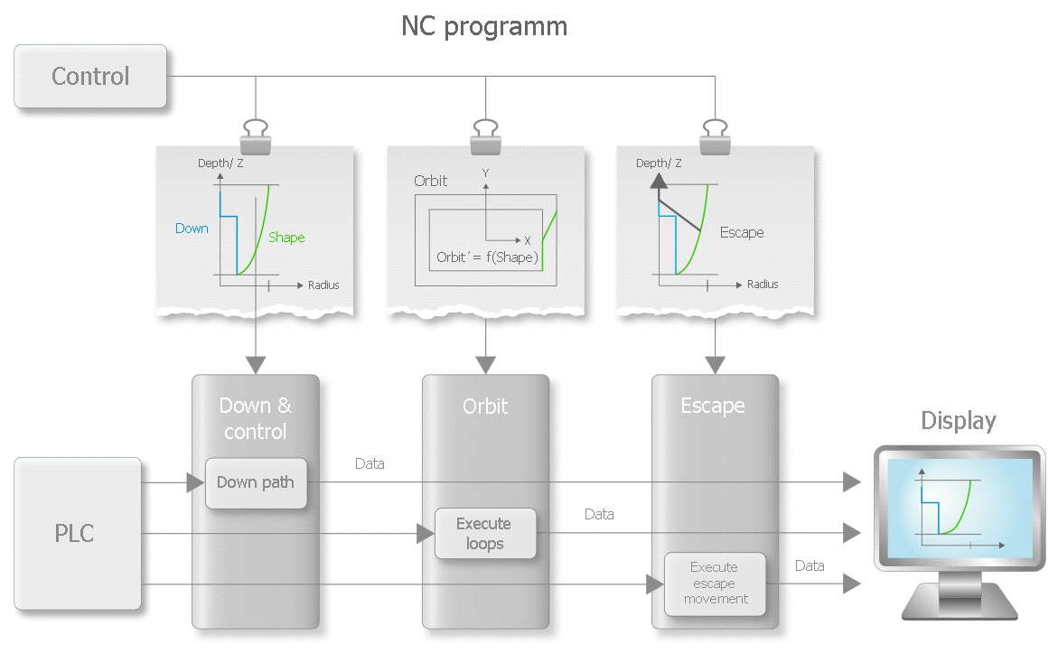
The down channel assumes the task of the main channel and commands and starts the other two channels. Among other things, the geometry of positioning and erosion on the path are executed in their own NC program. During the orbiting phase, only a two-dimensional contour may be programmed (see figure above).
The orbit channel simultaneously performs the motion on its programmed geometry in an endless loop. The X and Y coordinates returned to the down channel depend on the current position in the orbit channel and on the radius transferred from the down channel. The resulting three-dimensional motion is generated by superimposing both of the two-dimensional motions.
The escape channel is programmed in the same coordinate system as the down channel. This channel controls the escape motion of the electrode. There are different strategies to calculate an escape path during program runtime based on the current position in the down channel. The escape channel moves along this escape path. This allows the gap size to be set irrespective of program progress in the down channel. The velocity of the escape channel, just like the velocity in the down channel, is a variable that is controlled by the process and is specified by a spark generator. In addition, the escape channel is used to initiate the flushing process by means of a jump movement to enable an optimised flushing process, fast escape and a quick restart on the escape path.
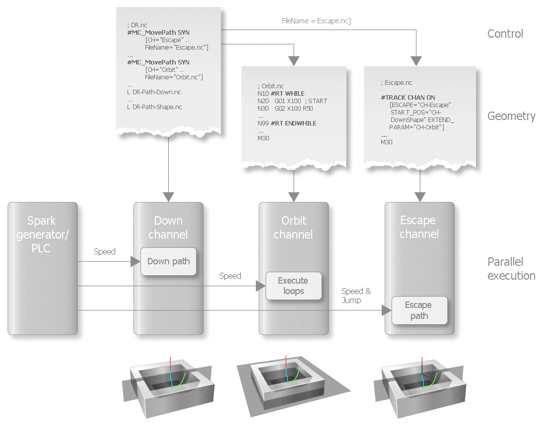
The approach using separate channels allows progress in the RZ plane to be independent of the progress of the orbit motion and enables constant adjustment of the gap size using the escape channel.
It is also possible to move on an orbit disc at constant position in the down channel and at the current velocity in the orbit channel. By controlling the escape velocity, the gap distance and ultimately surface quality can be optimised at disc height (see Disc management).
Controlling the EDM process
In CNC, the EDM process is entirely controlled by the spark generator via the PLC. The PLC distributes the specified generator velocity via the external velocity interface (ext_command_speed) control unit) to the individual channels. By setting the real-time task to “SWITCHED” [FCT-C39/ CNC scheduling], the velocity value specified by the PLC has the same effect on the generated command value from the CNC in the same cycle.
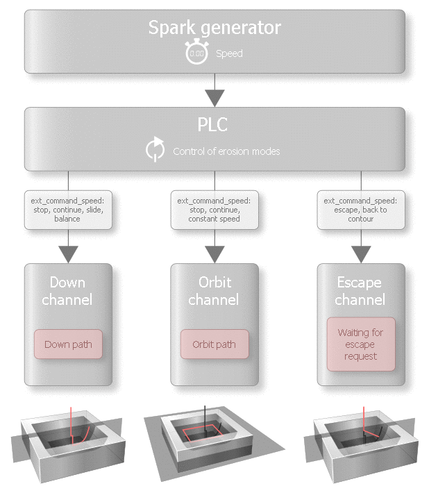
The distributed specified velocities provide the possibility of implementing different erosion modes using the same CNC architecture. Below are two examples and the section Applications contains more examples that explain exactly how these erosion modes need to be programmed.
Alternating orbiting
Horizontal discs are generated at a specific velocity in the orbit channel and at a constant position in the down channel. Discs can be executed at different heights by motion in the down channel.

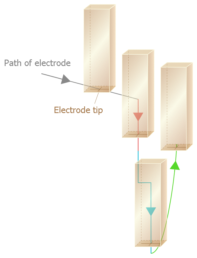
Star orbiting
As a result of the independent orbit channel, it is also possible to execute a motion on a perpendicular plane at constant position in the orbit channel and existing motion in the down channel, for example to obtain the required quality of surface finish at the corners of a geometry. A tool motion based on this machining strategy is shown in the figure below.
