Process
To ensure that the cycle is executed successfully, the following requirements must be met.
- The tool radius is defined by V.G.WZ_AKT.R
- Tool length compensation is active.
- The spindle speed must be selected before the cycle is started.
- The slot can be reached without collision starting from the current position at the height of the retraction plane.
- The slot must be approachable without collision along its opening with the clearance [2*V.G.WZ_AKT.R+@P13].
- A maximum of 3 systems may be active or defined when the cycle is called to ensure that sufficient machining coordinate systems (#CS) are available for the cycle.
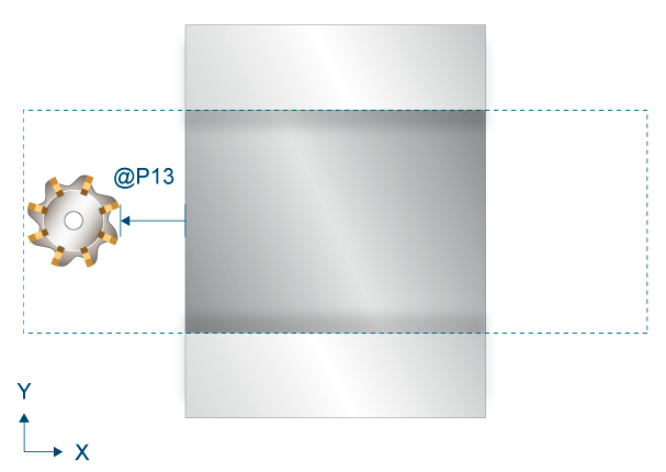
At the start, the start point in the XY plane is approached at the height of the retraction plane. At this start point, the milling cutter has the safety clearance to the blank as set in @P13. The starting point lies in the direction of the negative X axis relative to the reference point (at orientation angle 0).
After executing the cycle, the milling cutter retracts to its position when the cycle was called.
The slot must be approachable without collision along its opening with the clearance [2*V.G.WZ_AKT.R+@P13]. The dashed area in the graphic below is travelled during the cycle at machining height.
Roughing process
A distinction is made with roughing between trochoidal milling (@P32=1) and plunge milling (@P32=2).
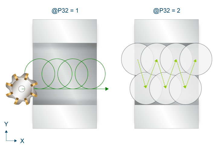
Trochoidal milling (@P32=1):
The feed is first to the safety plane at rapid traverse along the Z axis followed by a feed to the machining height at the feed rate. At this start point, an iterative feed takes place to the new machining height at the feed rate defined in @P40 until the slot depth @P4 is reached with the addition of the finishing allowance at the base (@P15). The maximum feed in Z per pass is the maximum feed in Z at the maximum value defined in @P5.
The slot is repeatedly milled incrementally in a circular movement for each machining height. The clearance of the paths between each circumferential pass never exceeds the value of the maximum feed in XY defined in @P6.
To avoid jerky movements in the milling path and thus relieve the machine tool, it may be useful to activate polynomial smoothing during roughing. This also leads to an accelerated execution of the milling cycle. The parameterisation of polynomial smoothing should be made dependent on the selected finishing allowance in order to avoid damage to the outer contour. To avoid residue, the maximum infeed in XY must then be reduced.
The milling cycle with polynomial smoothing can be called as follows:
#CONTOUR MODE [DEV, PATH_DEV = V.G.WZ_AKT.R / 10 ] ( Parameterisation )
G261 ( Activation of polynomial contouring )
L CYCLE [NAME = SysMill... ] ( Roughing )
G260 ( Deactivation of polynomial contouring )
L CYCLE [NAME = SysMill... ] ( Finishing )
M30
Plunge milling (@P32=2):
The milling cutter is fed incrementally in the XY plane at rapid traverse at the height of the safety clearance. The clearance between two feeds never exceeds the value of the maximum feed in XY defined in @P6. Milling takes place along the Z axis for every iteration until the slot depth @P4 is reached with the addition of the finishing allowance at the base (@P15).
Prefinishing process
Prefinishing is used to remove residue from the roughing process. The finishing allowances are not removed by milling. The milling cutter is iteratively fed up to the new machining height at the feed rate defined in @P40. The feed in Z per pass is the maximum feed in Z at the maximum value defined in @P5. The slot edge is milled linearly at the feed rate defined in @P20 for every new machining height.
Finishing process
As with prefinishing, however, the finishing allowances (@P15 and @P16) are removed here. The feed rates for finishing are defined in @P22 and @P23.