Parameterisation
Required input parameters
Input parameters | Description |
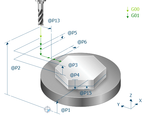
@P1 | Reference plane (absolute) |
@P2 | Retraction plane (absolute) |
@P3 | Safety clearance in Z (relative to reference plane/machining height) |
@P4 | Depth (relative to reference plane) |
@P5 | Maximum infeed Z (unsigned) |
@P6 | Maximum infeed in XY (maximum 2*V.G.WZ_AKT.R) |
@P44 | Number of edges (corners) |
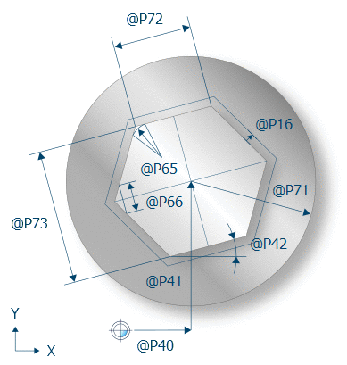
@P71 | Radius of round blank |
@P72 | Edge length |
Optional input parameters
Input parameters | Description |
@P13 | Safety clearance to blank in the XY plane (relative) Default value is the tool radius |
@P15 | Finishing allowance at base Default value = 0 |
@P16 | Finishing allowance at edge Default value = 0 |
@P20 | Feed rate for milling operation (specified in mm/min, inch/min) |
@P21 | Feed rate for infeed in Z (values in mm/min, inch/min) |
@P22 | Feed rate for finishing for milling in the XY plane (specified in mm/min, inch/min) The default value is the feed rate for roughing |
@P23 | Feed rate for finishing for infeed in Z (specified in mm/min, inch/min) The default value is the feed rate for finishing for milling in the XY plane |
@P25 | Spindle speed for finishing (specified in rpm) Default is the spindle speed at cycle call |
@P30 | Machining direction "ClimbMilling" or 0: Down milling (default) "UpCutMilling" or 1: Up milling |
@P31 | Machining mode: "Roughing" or 1: Roughing "Finishing" or 2: Finishing "Roughing+Finishing" or 3: Roughing and finishing (default value) |
@P40 | Position of centre in X Default value is the current position |
@P41 | Position of centre in Y Default value is the current position |
@P42 | Angle of inclination of spigot Default value = 0 |
@P65 | Corner radius of spigot Default = 0 |
@P66 | Chamfer length of spigot (alternative to corner radius) default value = 0 |
@P73 | Width across flats (alternative to corner length) |
@P135 | Maximum infeed in XY for edge finishing Default value is the maximum infeed in XY for roughing |
@P170 | Maximum infeed in XY for base finishing Default value is the maximum infeed in XY for roughing |
@P171 | Feed rate for plunging in previously milled areas Default value is the feed rate for roughing for the infeed in Z |
The function of the parameters acting in the XY plane results from the graphic below:
It is recommended to use the Syntax check to verify whether the input parameters are correctly assigned.

The majority of parameters which mainly refer to the Z axis are displayed in the graphic below:
