Dynamic optimised contouring
Contouring types with corner deviation and interim point define the contouring curve by a direction- and curvature-continuous connection between two motion blocks. This contouring curve referred to the axes may result in a fluctuation in acceleration.
When the possible dynamic data is considered with reference to the axes (acceleration, jerk), the contouring curve is defined at uniform acceleration (minimum jerk) of the two axes. By utilising maximum axis acceleration, the duration of the contouring curve is reduced.
Syntax of parameterisation: |
#CONTOUR MODE [ DIST_SOFT [PATH_DIST=..] [TRACK_DIST=..] [ACC_MAX=..] [ACC_MIN=..] [RAMP_TIME=..] [DIST_WEIGHT=..] ] |
DIST_SOFT | Dynamic optimised contouring |
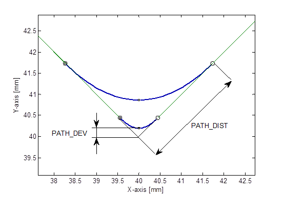
PATH_DIST=.. | Corner distance of pre-block and post-block (symmetrical) in [mm, inch *] after which a deviation from the original contour is allowed. The definition refers to the motion path of the feed axes. Default value: 1 mm Monitoring off: -1 mm *when P-CHAN-00439 is active |
TRACK_DIST=.. | Corner distance to pre-block and post-block in [°] after which non-feed axes (tracking axes) may deviate from the original contour. Default value: Value is adopted automatically from PATH_DIST provided this value was not explicitly specified (since program start). Monitoring off: -1 ° |
ACC_MAX=.. | Percentage in [0%-100%] of maximum axis acceleration (machine data) which may be used by the contouring curve. Default value: 100% |
ACC_MIN=.. | Percentage in [0%-100%] of maximum axis acceleration (machine data) which should be used by the contouring curve. If the specified corner distance (see PATH_DIST) is not maintained, the acceleration is increased to maximum value (ACC_MAX). Default value: 50% |
RAMP_TIME=.. | Percentage weighting of the ramp time in [0%-10000%]. Default value: 100% |
DIST_WEIGHT=.. | Influences the split of contoured linear blocks in [0%-100%]: In the 0% pre-definition, all blocks are halved; at 100%, the split ratio corresponds to the lengths of adjacent blocks. This value can be used to combine the two methods by percentage. Default value: 0% |
Restrictions:
- If a circular block is used for contouring, the contouring curve is calculated with corner distance without dynamic optimisation.
- The calculation uses only one ramp time (maximum value of the four individual ramp times).
- No processing of kinematic transformations. In this case, calculation is performed with corner distance without dynamic optimisation.
- In many cases, weighting the corner distances by the parameter DIST_WEIGHT depending on the pre-/post-blocks results in an optimised utilisation of the available block length.
When axis-specific contouring is executed, the corner distances of the pre-block and post-block are always identical (symmetrical). If the maximum corner distances are also limited on the half block motion path, a shorter contouring section and therefore a lower contouring velocity results for longer motion paths due to the shorter preceding/following motion path.
If the length of the pre- and post-blocks are considered in the calculation of the maximum corner distances, the contouring zone can be increased.
Programing Example

Dynamic optimised contouring
Comparison of contouring of a 90° corner with the methods:
- Dynamically optimised contouring (DIST_SOFT):
N010 #CONTOUR MODE [DIST_SOFT PATH_DIST=12]
N020 G0 X0 Y80
N030 G261
N040 G01 X40 Y40 F2.5
N050 G01 X80 Y80
N060 G260
N070 M30
- Contouring with corner deviation (DEV):
N010 #CONTOUR MODE [DEV PATH_DEV=0.2]
N020 G0 X0 Y80
N030 G261
N040 G01 X40 Y40 F2.5
N050 G01 X80 Y80
N060 G260
N070 M30
Comparison of contouring curves: