Switch via NC command
The slave can track the dynamic coordinate system of any master. It can be controlled by an NC command.
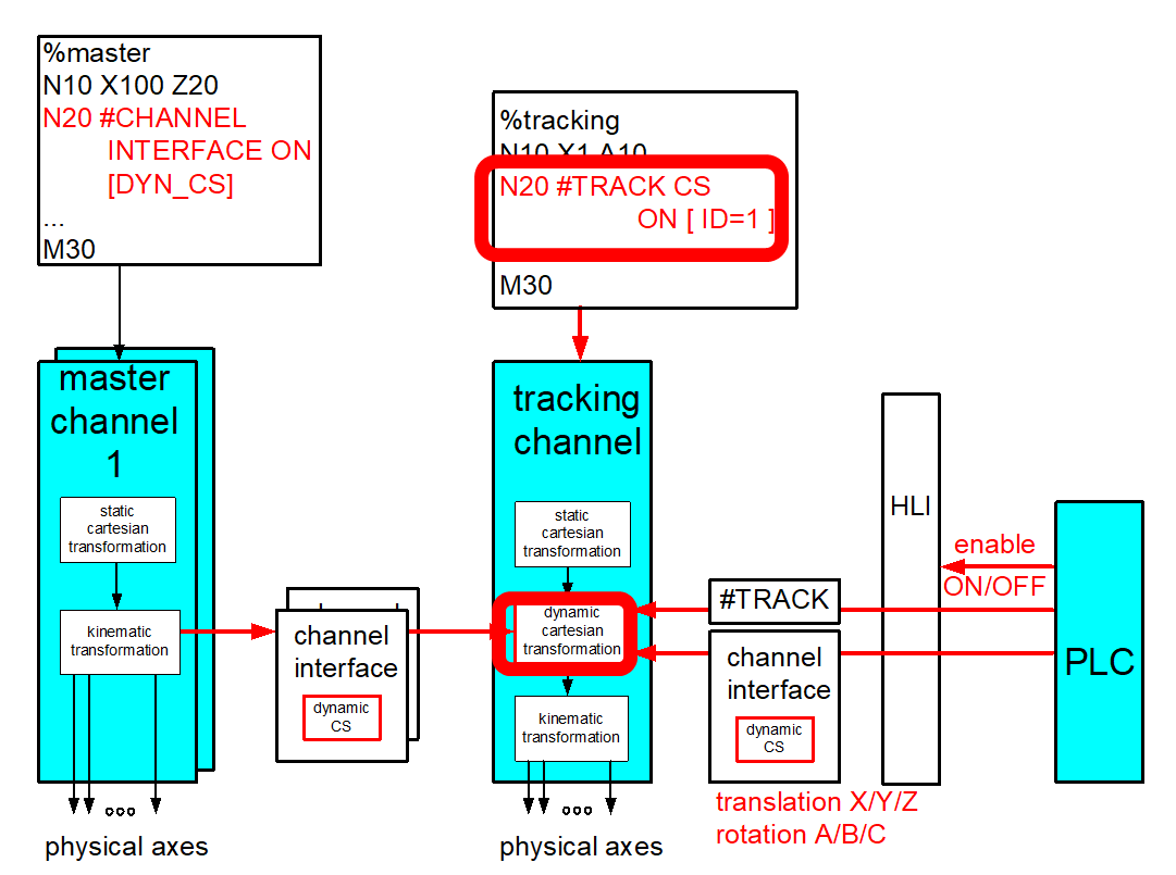
The enable command has the following syntax:
#TRACK CS ON [ CH=.. | ID=.. [SET_ZERO | ABSOLUTE ] [OPTION=..] [X=.. ] [Y=.. ] [Z=.. ] [A=.. ] [B=.. ] [C=.. ] ] [SIMU] [LOG_FILE=..] ] |
CH=.. | Source of the dynamic coordinate system which is to be tracked. [1;12]: CNC channel number which the dynCS indicates. |
ID=.. | Source of the dynamic coordinate system which is to be tracked. 0: PLC Interface [1;12]: CNC master channel number which the dynamic CS indicates. |
SET_ZERO / | The current positions of the master are signalled to the decoder and can be calculated in the NC program as follows. This can occur implicitly by #TRACK CS ABS or explicitly by the channel variable V.G. TRACK_CS.X/Y/Z/A/B/C. |
OPTION=.. | Options which must be tracked: 0: translation and rotation are considered. (default) 1: only translation is tracked. |
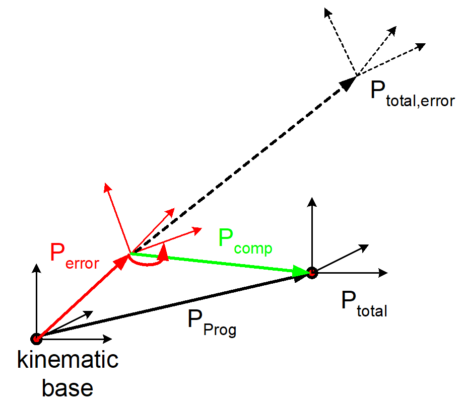
KIN_BASE | Fluctuations (red in the figure) in the kinematic based are compensated so that the slave TCP can be maintained at a stationary position. First specify the erroneous X/Y/Z offset and then the rotation C-B-A of the kinematic base. |
FILTER=.. | If the input parameters are not 0 when the function is activated/deactivated, this would lead of a position jump in the programmed path contour. To prevent this, the specified translation/rotation can be coupled/decoupled softly by a filter and smoothed over the specified cycles. == 0, Filter is off. > 1, Filter is activated with explicitly specified filter time. If not specified, the filter is activated at default filter time = 200. |
WAIT | When the filter is active, the program waits until the coupling is completely activated to execute the next NC row. If this mode is not specified (default), coupling is executed “on the fly”. |
X | Y | Z | A | B | C | Additional static offset / rotation of error coupling point referred to kinematic base (KIN_BASE=1). Static offset between master and slave (KIN_BASE=0). |
ROT_TRANS | The error is specified by an offset and a rotation. First measure the offset and then the rotation. If the offset is measured in the coordinate system which is already rotated, this can be specified by the following setting. |
Offset / rotation X | Y | Z | A | B | C
Specify an additional offset / rotation has different meanings depending on the application:
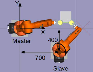
Application: Moved workpiece
This parameter specifies the static position offset of the slave to the master. In the example below this would be:
#TRACK CS […X=400 Y=700 C= - 90…]
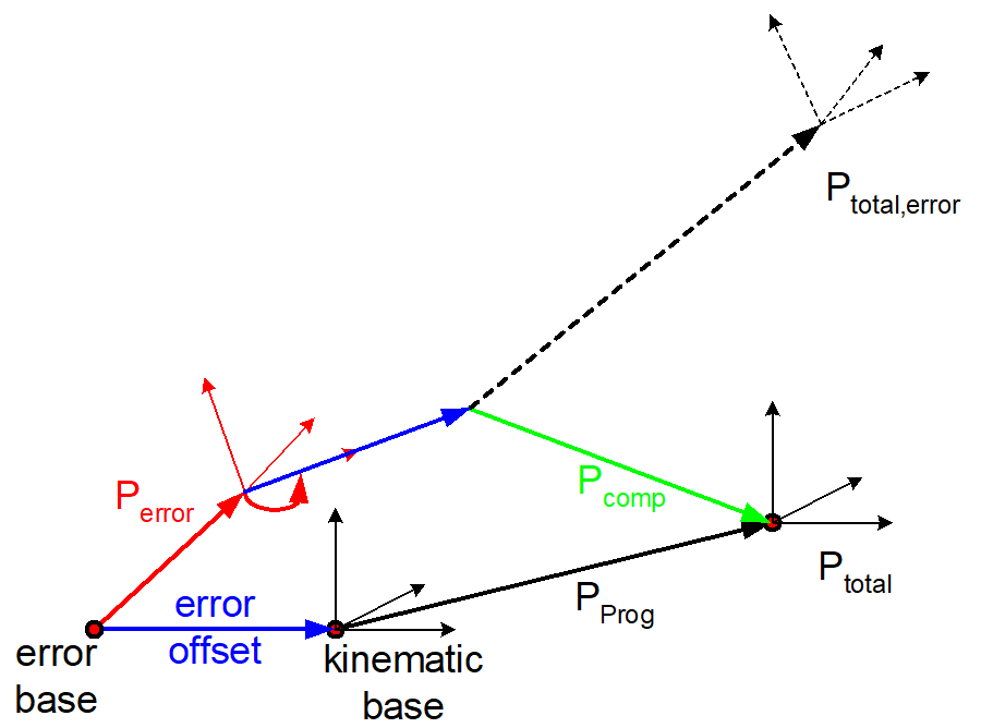
Application: Fluctuations in kinematics base
These parameters specify additional static offsets / rotations (blue in the figure) between the error angle of attack and the kinematic base.
#TRACK CS […KIN_BASE …X=200 …]
The disable command has the following syntax elements:
#TRACK CS OFF [ WAIT ] |
WAIT | When the filter is active, the program waits until the coupling is completely deactivated to execute the next NC row. If this mode is not specified (default), coupling is executed “on the fly”. |
Programing Example

Switch via NC command
%TrackCS
; Dynamic CS received by PLC
N6076 #TRACK CS ON [ID=0 OPTION=1 FILTER=1000]
N6085 G01 X0 C0
N6080 X0 Y0 Z0 A0 B0 C0
N6077 #TRACK CS OFF [WAIT]; Wait until coupling is fully off
M30