Tool orientation (P-TOOL-00146)
P-TOOL-00146 | Tool orientation by specifying a vector |
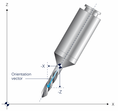
Description | In 2.5D mode, if a tool is in parallel or at a fixed angle to the main axes of the machine coordinate system, this orientation can be described as a vector. Vector components are defined in the direction of the tool tip, either scaled or unscaled, starting at the tool mount point. When selecting the tool, the orientation vector is used to form axis-specific offset components of the tool length.
|
Parameter | wz[i].orientation_vector[j] where j=0...2 |
Data type | REAL64 |
Data range | MIN(REAL64) ≤ orientation_vector[j] ≤ MAX(REAL64) |
Dimension | ---- |
Default value | 0.0 |
Remarks | The vector position always refers to the machine coordinate system. If the orientation vector is not assigned (=0), the tool length is considered using the default method (plane-specific, #TLAX). Parameterisation example: Tool T1 is oriented opposite to the positive Z axis direction: wz[1].orientation_vector[0] 0 wz[1].orientation_vector[1] 0 wz[1].orientation_vector[2] -1 |