General parameters
General parameters include:
- Geometry of the probe and calibration sphere
- Safety distances for pre-positioning and measurement run
- Velocities for pre-positioning and measurement run
- Kinematics used
- Path to save the measurement results in "message.txt" on the default path
Geometry | Unit | Meaning |
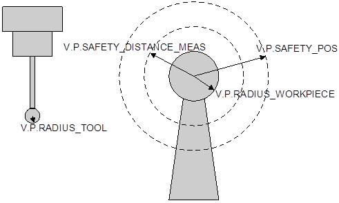
V.P.RADIUS_TOOL | mm | Radius of probe tip (clamped in the spindle) |
V.P.SAFETY_POS | mm | Safety distance about the calibration sphere during pre-positioning |
V.P.SAFETY_DISTANCE_MEAS | mm | Safety distance around the calibration sphere during measurement Must be large enough to reach measurement speed. |
V.P.RADIUS_WORKPIECE | mm | Radius of the calibration sphere (placed on bench as workpiece) |
V.P.MEASURING_FEED | mm/min | Velocity for measuring (G100 blocks) |
V.P.POSITIONING_FEED | mm/min | Velocity for positioning |
V.P.KIN_TYP | - | Kinematic of the machine |
V.P.KIN_TYP_VARIANT | - | Variant of the kinematic if, for example, several kinematics can be grouped by one number, as with kinematic 90 |
#FILE NAME [MSG = "…"] | String | Path to save measurement data |
V.L.PRINT (optional) | - | Output of a log in the parameterised file, 0 = no log, 1 = German, 2 = English |
V.P.MAX_PRECISION (optional) | mm | Maximum permitted deviation of measurement errors |
V.P.LIST_FORMAT | - | Output formats: 0 = XML, 1 = TwinCAT 2, 2 = TwinCAT 3 |
The radii of the probe tip and calibration sphere only serve to calculate the motion paths and are not used to calculate offsets. It is therefore sufficient to enter approximations for these radii. The meaning of the geometry parameters is described in the figure below.
The first measurement movement is in the negative Z direction. The measurement path is determined by the parameters entered by the operator and is incremental from the starting point:
Z = -(V.P.RADIUS_TOOL+V.P.SAFETY_DISTANCE_POS + 2*V.P.RADIUS_WORKPIECE)
Example

Probe radius (as tool) V.P.RADIUS_TOOL = 3Positioning safety distance: V.P.SAFETY_DISTANCE_POS = 20Calibration sphere radius (as workpiece): V.P.RADIUS_WORKPIECE = 15
The resulting NC block is:
G100 G91 Z-[3+20+2*15]
A distance of -53 mm is traversed in Z, then the distance between the sphere and the probe at the start must be smaller than 53mm.
Example
The safety distance must be large enough to reach the correct measuring velocity. Otherwise, deviations may occur due to the velocity-dependent switching signal.