Description
Activation
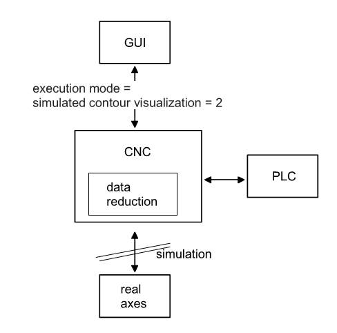
Rapid contour visualisation is activated by transferring the program start option SOLLKON on the HLI to the controller at program start (see documentation on the HLI).
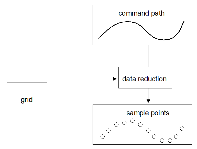
No axis motions are executed with Rapid Contour Visualisation. Visualisation data is output in a reduced grid. The required interpolation point grid or the permitted secant error must be specified for the interpolation. The NC program is executed faster as a result of the sample grid.
Programmed dwell times (G04, #TIME) are ignored.
Applications
Simulation can be used for following applications, among others:
- “Syntax check“ using the entire CNC channel. As opposed to the syntax check mode, all modules in the NC channel are active during the simulation except for the position controller. This permits the detection of errors that are not detected during the syntax check, e.g. compensation motions during tool radius compensation or crossed software limit switches.
- Advance visualisation of an NC program (offline).
Sample grid
Depending on the motion block used (straight/curved), the interpolation point grid can be specified for the interpolation either
- by specifying a maximum interpolation point interval
- or by specifying a maximum path error
This can be defined in the following parameters:
Parameter | Format: | Description | Index-Group | Index-Offset |
mc_contour_visu_grid_w | UNS32 | Output grid for nominal contour visualisation for linear blocks (G00/G01) in [0.1 µm] | 0x2010<c>
c element [1; max. channel] | 0x89, 0x8a |
mc_contour_rel_curv_error_w | REAL64 | Maximum relative path error in [0.1%] for nominal contour visualisation of circles or polynomials | 0x2010<c>
c element [1; max. channel] | 0x8b |
mc_contour_abs_curv_error_w | REAL64 | Maximum absolute path error in [0.1 µm] for nominal contour visualisation of circles and polynomials | 0x2010<c>
c element [1; max. channel] | 0x8c |
The target points of every NC block are always output.
Interpolation point grid for linear blocks
For linear blocks the interpolation point interval for interpolation is specified directly. As a consequence the axis dynamics and the programmed commanded velocity are not considered.
The programmed linear block is also output for each linear block if it does not lie on the set interpolation point grid. This means that the corners of a contour are always displayed.
If a linear block is shorter than the set interpolation point grid, the end point is not output.
Interpolation point grid for curved contour elements
An
- absolute secant error
- and a relative secant error
.
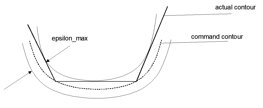
εmax = r*εrel for: εrel <= εabs
εmax = εabs for: εrel >= εabs
The resulting second error is the smaller of the two values.
Stop conditions
The execution of an NC program can be stopped by internal and external influences.
Internal stop conditions are NC commands which can only be terminated by user interaction. One example is a programmed stop (M00). The channel parameter P-CHAN-00183 prevents program execution from being stopped.
In case of external stop conditions, the user himself initiates the stop of an NC program execution. Examples include:
- Feedhold via the PLC interface
- Technology function not acknowledged
External stop conditions are always effective. The user must therefore make sure that program execution is not stopped.
Notice

As opposed to Syntax Check [see functional description FCT-C9] it is not possible to continue program execution after an error occurs.
When an error occurs, a reset must be triggered in the channel and the program must be restarted after the error is rectified.
Output
Generated visualisation data can be read by CNC objects. Motion blocks are divided and axis positions are output depending on the grid set.
Axis positions can be output in 2 ways:
- Display of axis coordinates including offsets (machine coordinates)
- Display of absolute coordinates without offsets (programmed coordinates)
Select the data to be output in the Start-up parameters P-STUP-00039.