Description
The controller can supply the axis positions for the graphic display of machine movements and visualise them by means of a user program or in the graphic user interface.
In normal mode, axis positions are supplied in the CNC as display data in the interpolation cycle. To simplify visualisation, the volume of data supplied can be reduced by output of the relevant positions for visualisation, e.g. the exact end point of a contour element. Corners also remain identifiable as corners in the reduced visualisation data. The correct visualisation of corners is also possible if only very few points are declared if display is intended to be very rapid.
Different operation modes of contour visualisation
Dry run
In dry run mode, the NC program is decoded normally and the positions are interpolated. Axis motions are not forwarded to the position controller, meaning that there is no axis motion.
Rapid contour visualisation
The controller operates in simulation mode without real axis motion; the CNC program is processed rapidly. This function samples programmed contours and corners are all retained.
This considerably decreases the number of interpolation points for visualisation.
No real axis motion occurs.
Online contour visualisation
The controller operates in normal mode and CNC program execution is not affected. Position values are supplied to the contour visualisation interface in a coarser grid for visualisation.
Scene
The sequential kinematic chain is defined in the CNC program. A graphical object can be positioned in any coordinate system of the kinematic chain (LINKPOINT). Coordinate system movement is logged via an interface. The movements of graphical objects can be logged in kernelCAM or another system.
The table below contains a comparison of modes:
Execution mode | Data reduction before interpolation | Data reduction after interpolation | Coordinate system of output data | Special features | Viewer |
1. Dry run | - none - | - none - | PCS | Normal program execution without real axis motion |
|
2. Rapid contour visualisation | Geometric grid, abs./rel. secant error | No data reduction after interpolation; no interpolation points are generated if they do not lie on the visualisation grid. | WCS or ACS | possible without real axis motion. Rapid program execution | kernelCAM in preparation |
3. Online contour visualisation | - none - | Geometric grid, abs./rel. secant error | WCS or ACS |
| kernelCAM in preparation |
4. Scene | - none - | Time sampling in frames per second | MCS=W0 any point on the kinematic chain, also TCP | Available for any serial kinematics Kinematic chain must be initialised in the NC program | VirtuosV as vCAM |
Coordinate systems
A number of different coordinate systems are available for individual interfaces. The following definition is used here:
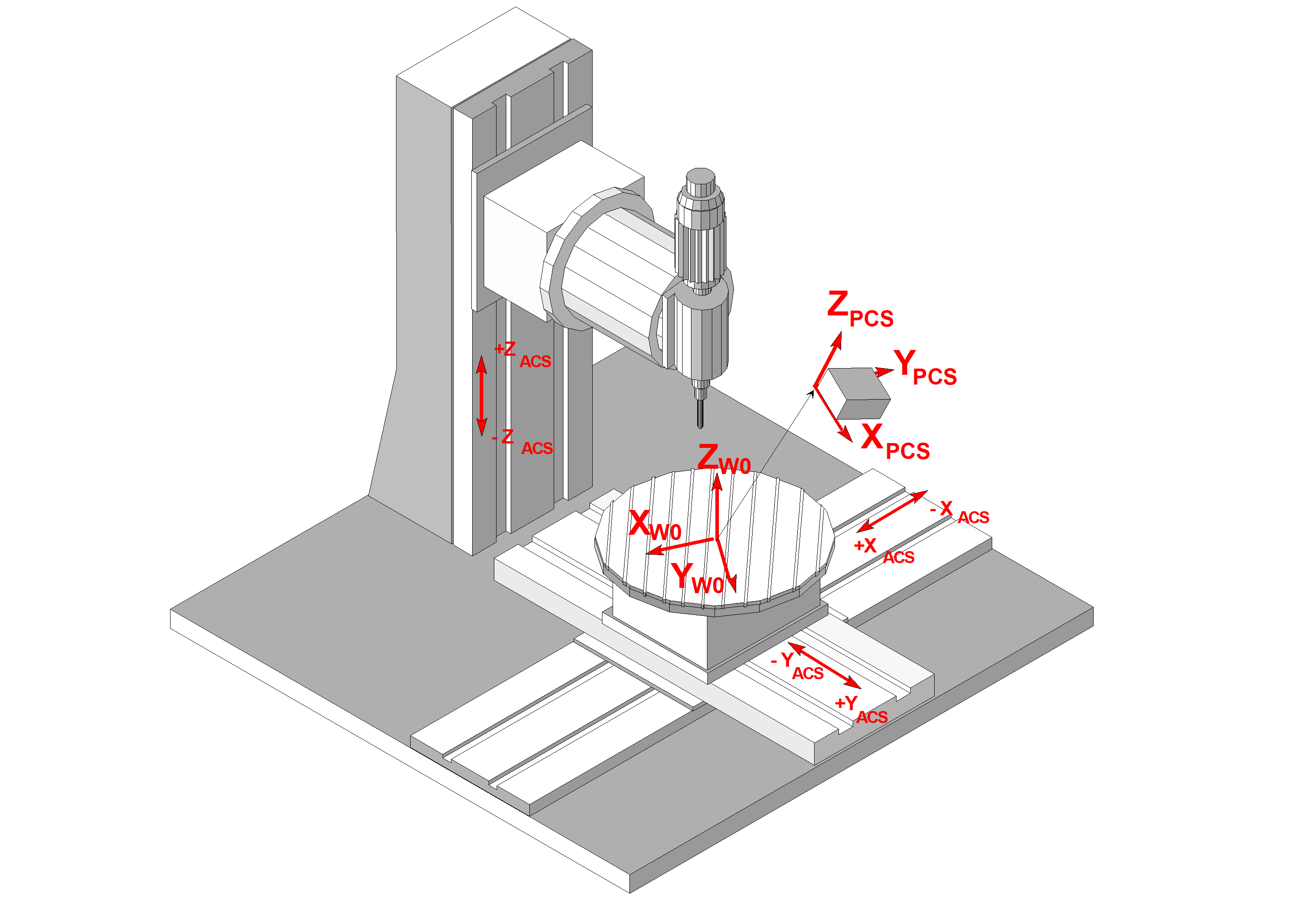
ACS: | Axis Coordinate System |
W0: | Base Workpiece Coordinate System, Cartesian base coordinate system of the machine referred to workpiece clamp position |
PCS: | Programming coordinate system |