Parametric model according to DIN ISO 230 and ISO TR 16907
Classic compensations (leadscrew error, crossing and error compensation) determine their compensation values by means of a simple lookup operation in one or multi-dimensional tables. The compensation value of the affected axis then depends on:
- the current value of the axis itself (ssfk) or
- only the value of another axis (crosscomp) or
- the values of two axes (crosscomp2).
The decisive drawback of this approach is that it cannot be generalised in practice for higher dimensions since the required lookup tables would be too unwieldy and measuring the machine would take too long. A 5-dimensional table would be needed to compensate adequately for a 5-axis machine ("crosscomp5"). 10 interpolation points per axis would result in 105 grid points.
The parametric approach avoids this weakness by including information about the machine that is ignored by the lookup approach. A kinematic model of the (inexact) machine is created by using the given parameters. Then the compensated axis values are calculated from the known target position of the tool by inverting the model.
The Volumetric Compensation model works with two kinds of error parameters:
- Position errors
- Component errors
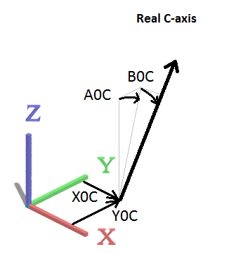
Position errors
The position errors of an axis describe how strongly the position and orientation of an axis deviate from their ideal values (position deviation is only relevant for rotary axes). In this way, global aspects of the machine, for example the rectangularity of axes, can be detected.
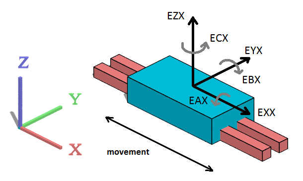
Component errors
Component errors specify which deviations a slide experiences when it is guided along an axis. The slide can be shifted with respect to its target position in each of the three spatial directions (EX*, EY*, EZ*) and can be inclined with respect to its target orientation (EA*, EB*, EC*). These errors are typically provided in a one-dimensional lookup table.