Example with MOS_TS
Output of the M function before the block, no synchronisation. With this method the CNC provides a time offset referred to the block transition point.
Due to sampling at cycle time tcycl, the output point of an M function at interpolator level lies within the time of the sampling rate but this is offset in time to the block transition point by maximum one sampling cycle.
The exact output time can be calculated and executed in the PLC by using the tracked time offset of the M function.
See also [HLI], Section “Data of the M function/H function“ for CNC versions up to Build V2.11.2800
or “Data of the M function/H function“ for CNC versions as of Build V2.11.2800.
Initialisation in the channel parameter list:
m_synch[..] 0x00040000 (MOS_TS)
Programing Example

MOS_TS
N10 G01 X25 G90 F5000
N20 X50
N30 M25 (M25 MOS_TS)
N40 X100
N50 X200
M30
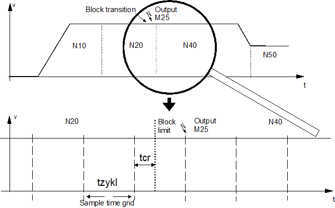
M function output
The M function is programmed at the block transition between N20 and N40. Due to the time-based sampling the sample point and therefore the output of the M function lags slightly behind the transition of the block limit.
- As a result, the M function is output with a maximum delay of one sampling interval.
- The offset of the programmed theoretical output time of the M function up to the last sampling cycle is output as deceleration value tcr.
Attention

For the correct entry of the time offset, the PLC interface must be read cyclically. Only this ensures the exact output of following M functions of type MOS_TS and a correct assignment within the time-based process.
Notice

The function for the exact output instant is typically executed in the PLC by using a special high- resolution timer hardware.
Attention
The sampling time offset, calculated by the CNC, is not passed to the HLI if the synchronisation type MOS_TS is used in axis-specific M function programming (see example).
N10 G01 X25 G90 F5000
N20 X50
N30 X[M25] axis specific output M25 (MOS_TS)
N40 X100
N50 X200
M30
Example

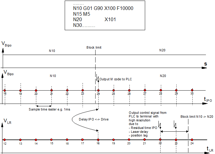
Exact path-synchronous triggering of I/Os
During a cutting operation, a laser (100 µm beam width) is to be switched on/off at the exact position. The tolerance is within 10 µs or within ½ beam width (=50 µm). The time-related resolution of the CNC interpolation cycle (typically 1 ms) is not sufficient for this. The problem can be solved by using high-resolution timer hardware and algorithms in the PLC.
The dead time in the CNC to drive system chain must be greater than the dead time in the system chain to the laser system.
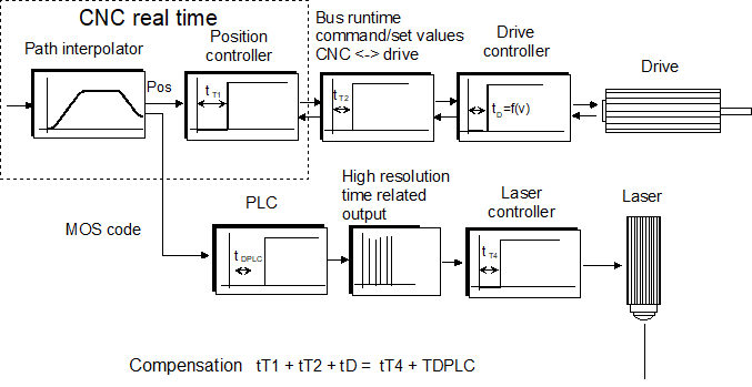
This case is based on a laser system with a typical dead time of 800 µs. With the CNC - drive positioning chain, the typical dead time is 5 sample cycles ((5 x 1 ms = 5 ms).
The positioning control system in the drive operates with no position lag (active feedforward control). However if necessary, position lag can be estimated.
The PLC takes into consideration the dead time of the positioning chain to control the laser with time TDPLC. As a result, the PLC delays the M code of the path interpolator supplied by the CNC by n cycles. The exact switching signal for the laser in the succeeding cycle is calculated in the PLC based on the interpolation data and the dead time and it is generated with a high basic clock-pulse rate (e.g. 1 µs) via a hardware terminal.