Band-stop filters
Frequency response
Bandwidth ΔΩ=f0 - fu within the stop band of the band-stop filter is defined by the cut-off frequencies f0 and fu. They are defined as frequencies where the amplitude drops by -3dB (~0.707). When a band-stop filter is configured, the bandwidth is determined by specifying the quality factor (filter[i].guete) . The quality factor is the ratio of the characteristic filter frequency to bandwidth ΔΩ:
For this reason, the frequency range f0-fu reduces as the quality rises. The following relationship exists between the characteristic frequency of the band-stop filter and the cut-off frequencies f0 and fu (geometric mean):
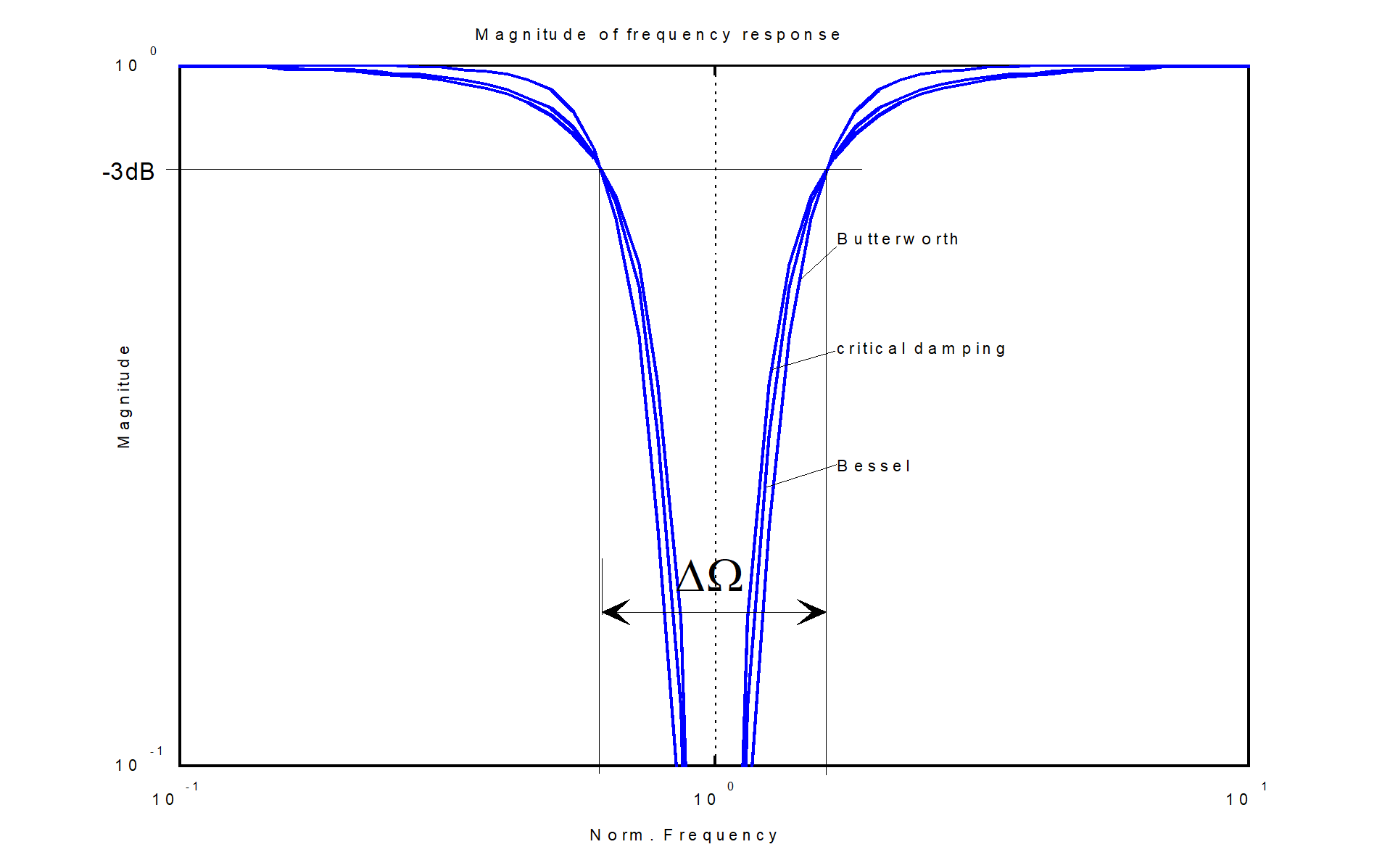
With band-stop filters, the filter prototype has only a slight influence on filter response.
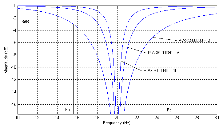
The figure shows the amplitude response of band-stop filters depending on the specified quality factor (2nd order, characteristic frequency fg_f0 = 20 Hz)
Response
In general notch filters tend to oscillate due to the strong weakening of the characteristic frequency. This also leads to axis overshoots at block transitions.
The higher the filter order or the smaller the cut-off frequency fg_f0, the greater the overshoot may be. However, in general this error is much smaller than the contour error that may occur by exciting a resonance frequency. This must be verified for a particular application. Otherwise the use of a band-stop filter makes no sense.
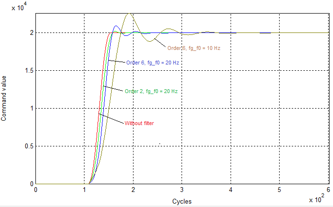
The figure shows the oscillation response of band-stop filters depending on the order and characteristic frequency.
Notice

Dynamic monitors may react in the CNC due to an overshoot of the band-stop filters. In this case either the axis dynamics must be reduced or a (slightly!) higher excess in command velocity must be permitted (see P-AXIS-00440).
Example

Axis filters: 2nd order band-stop, with characteristic frequency 20 Hz and quality 4:
filter[0].enable | 1 |
filter[0].order | 2 |
filter[0].prototype | BUTTERWORTH |
filter[0].type | BANDSTOP |
filter[0].fg_f0 | 20 |
filter[0].guete | 4 |
filter[0].share_percent | 100 |
Example
Additional interface: 3rd order band-stop, with characteristic frequency 17Hz and quality 1.8
Lr_param.add_interface.enable | 1 |
lr_param.add_interface.filter[0].enable | 1 |
lr_param.add_interface.filter[0].order | 3 |
lr_param.add_interface.filter[0].prototype | BUTTERWORTH |
lr_param.add_interface.filter[0].type | BANDSTOP |
lr_param.add_interface.filter[0].fg_f0 | 17 |
lr_param.add_interface.filter[0].guete | 1.8 |
lr_param.add_interface.filter[0].share_percent | 100 |