Lifting properties
The lifting motion is coupled to the path motion in this method. i.e. if the velocity of the path is changed, the LIFT motion changes to the same extent. Therefore, the same position of the path axes is identical to the position of the lift axis, regardless of the current velocity. This means that If the path motion is stopped (feed hold) or decelerated (override), the motion of the lift axis stops accordingly.
Within the LIFT range, the permitted acceleration on the path is defined so that the maximum permitted acceleration of the lift axis is not exceeded.
Waiting conditions (M functions with synchronisation, G04, M00, etc.) are possible during lifting/lowering. During the lifting motion, waiting conditions therefore lead to an interruption of the path and also of the lifting motion.
In the case of strongly bent curves (spline or polynomial contouring) or kinematic transformations, the original blocks can be further subdivided to improve planning the dynamics. This may lead to an increased number of blocks.
If there is an insufficient number of blocks (Look Ahead range)
- due to the large number of motion blocks of the path axes or
- due to the large number of technology functions (M functions),
premature lowering is avoided. Internally, a LIFT_END is added to the programmed height and a LIFT_START is then added.
At present, a maximum number of 20 CNC internal blocks (Look Ahead range) is considered between the lifting motion (START) and the lowering motion (END). A programmed motion block (G0, G1, G2, G3) normally generates an internal CNC block. Smoothing methods generate additional internal blocks.
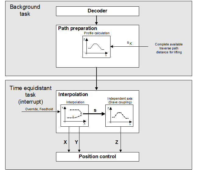
Planning the dynamics
The lifting motion is planned so that, at constant path velocity, the lift axis is lifted and lowered again with jerk limiting at its maximum acceleration.
If the path feed rate is changed during the lifting motion (feed hold, override, etc.), this leads to additional acceleration of the lift axis. As a result, lift axis acceleration may briefly exceed its maximum limit. However, the overall acceleration due to the feed rate change on the path and the lifting motion itself always remain within the specified overload range. Therefore, the following applies to the axis:
|aactive| < amax * overloadfactor
where

Notice

Planning lift axis dynamics requires slope type 'TRAPEZ' ([#SLOPE [...]). Slope type STEP may result in Z axis overload.
Path smoothing and lifting
The LIFT function can be programmed if a smoothing method was previously activated (1st case). The LIFT axis has velocity = 0 at the start and end of the lifting motion. Therefore, smoothing is temporarily suppressed at these points.
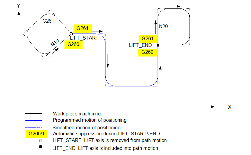
Exception: With CONTOUR MODE (G61, G261) the lift axis in the block does not move before lifting or directly after lifting (2nd case).
1st case: Lift axis motion before/after lifting
If the lift axis is moved before lift start (block N10) or directly after lift end (block N20), the contouring of all axes at the start or end of lifting is briefly suppressed.
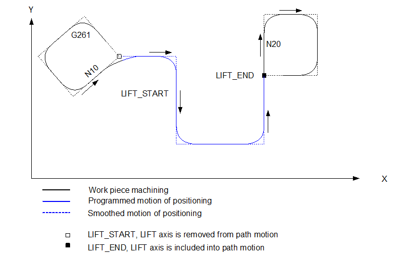
2nd case: No lift axis motion before/after lifting
The other axes can be smoothed if the lift axis is not moved before lift start (block N10) or directly after lift end (block N20).
Notice
Smoothing methods may not be additionally selected or deselected between LIFT_START and LIFT_END.