Wear compensation of tool radius
Grinding a contour
Use tool radius wear compensation (radius compensation) by preference to grind a contour at the same time as tool radius compensation.
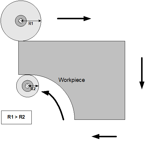
Grinding disc wear in the direction of the disc radius can be compensated continuously or discretely.
In the radius compensation processing type, wear is only considered for active tool radius compensation (TRC).
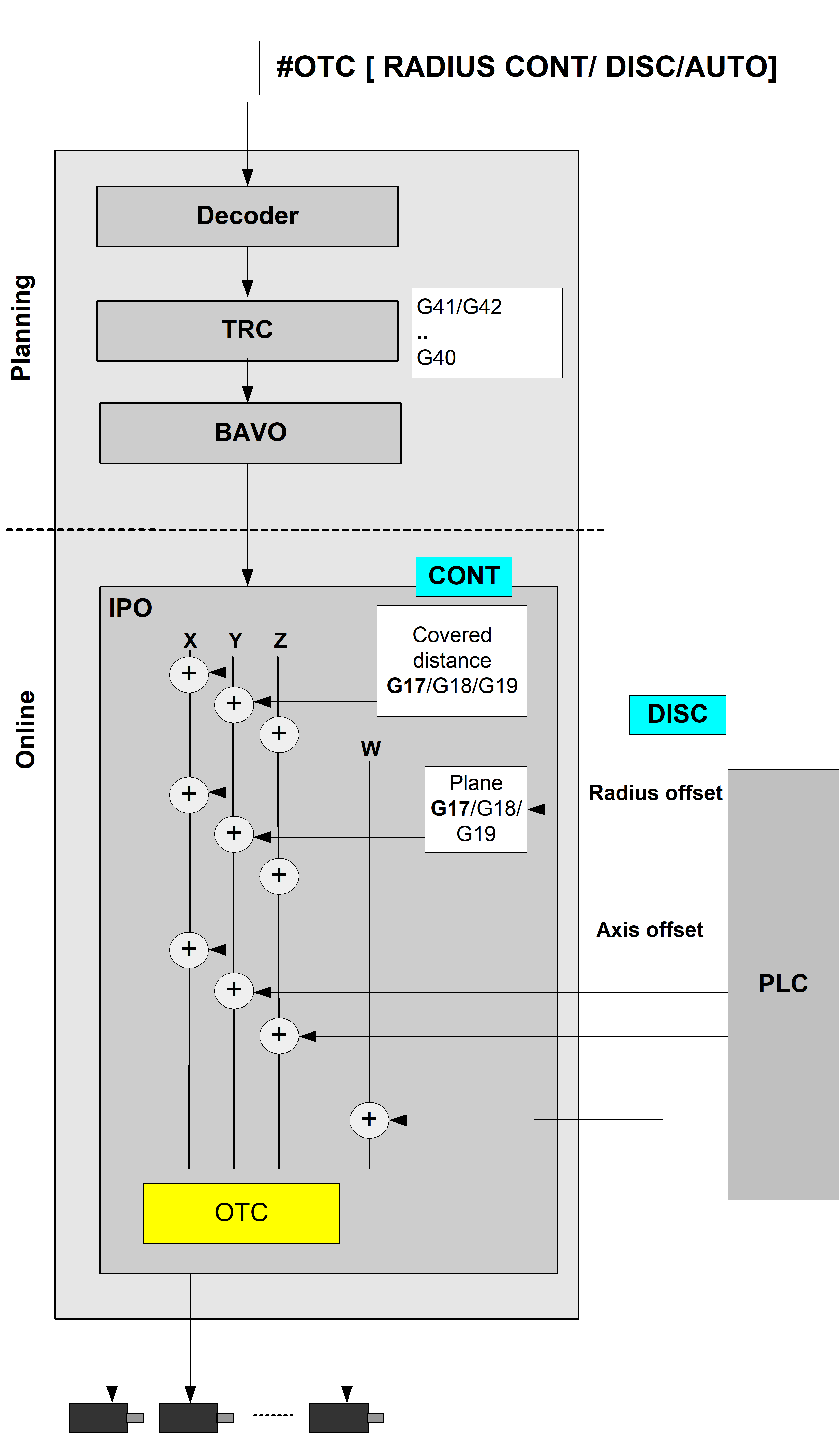
The figure below shows the tool radius wear:
Notice

The start-up movement in relation to the equidistant path after selecting TRC (G41/G42) is considered without wear.
Motion after deselecting TRC (G40) is also without wear.
Programing Example

General #OTC programming example
N10 F10000
N20 D1 (Data set selection for grinding wheel)
N30 G0 X0 Y0 Z0
N40 #OTC[RADIUS, AUTO] (define OTC processing type + mode)
N50 #OTC ON (select OTC)
N60 G41 G01 X50 (select TRC, wear-free movement)
N70 X1000
N80 G40 X50 (deselect TRC with path motion to reduce TRC)
N90 #OTC OFF (deselect OTC)
N100 G00 X50
N199 M30
Programing Example
OTC with discrete compensation
%wr_quad_disc.nc
N20 G17G90
N22 D1 G25 (Linear transition block)
N40 G1 X0Y0Z0 F600
N50 #OTC ON[RADIUS DISC]
N55 G42
N60 G1 X2
N70 G1 X102
N80 G26 Y100 (Circular transition block)
N90 X2
N95 Y0
N100 G40 G1 X0
N110 #OTC OFF
N99999 M30
Legend:
Green: | Path contour with active TRC without OTC offset |
Black: | Path contour with negative value for OTC radius offset |
Red: | Path contour with positive value for OTC radius offset |
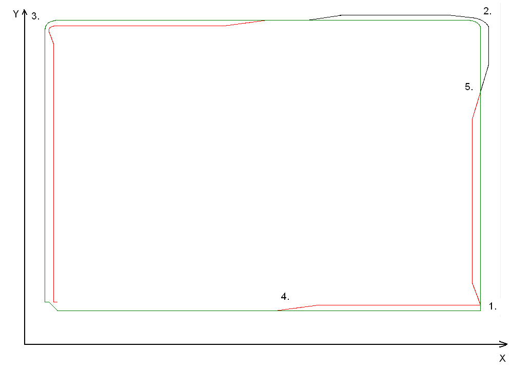
Explanation to the figure above (the discrete OTC offset applied is 2 mm)
- In this corner of the contour, G25 is active. The contour is not continuous. The predefined OTC offset is applied to another axis over several cycles.
- The TRC inserts a circular transition because of G26. But the OTC offset is so large that the increase in offset is unable to keep up with the continuous change in the contour.
- The OTC offset lags behind considerably.
- Increase the OTC offset
- Decrease the positive OTC offset and increase the negative OTC offset
The tool radius is influenced by the PLC.
Condition: After the OTCRadiusOffset control unit is active, the OTC radius offset can then be programmed accordingly for the build currently in use. This value is then added to each cycle perpendicular to the programmed contour.
PLC example code
(* Enable the OTC control unit for first channel *)
gpCh[0]^.bahn_mc_control.otc_radius_offset.enable_w := TRUE;
(* write radius offset in the first channel *)
gpCh[0]^.bahn_mc_control.otc_radius_offset.command_w := OTC_Offset;
Notice
A continuous contour path is recommended because changing the orientation of the predefined offset is not applied to the axis all at once but is distributed over several cycles.
Notice
On selection, the commands G41/G42 and #OTC ON can be swapped. On deselection, the sequence G40 before #OTC OFF must be maintained. The TRC modes G138/G139 make a path motion between the two commands absolutely necessary.
If error 90050 is output, the path motion does not exist when deselected with G138/G139.
The functionality of the RADIUS type is shown by the example of the G17 plane: