Rotate the coordinate system in the plane (#ROTATION ON/OFF)
This function rotates a coordinate system in the current plane (G17/G18/G19). Contours programmed in the machine coordinate system can be adapted quickly and easily to workpieces in offset positions.
Contour rotation acts directly on the programmed axis coordinates (contour) before all other contour-influencing functions, i.e. all offsets and mirroring operations are not influenced by the rotation and can be used as before (*).
Rotation may also be applied within an already rotated coordinate system (#(A)CS).
A change of plane with G17/ G18/ G19 automatically deselects an active contour rotation and a warning is output.
As a alternative to #ROTATION, contour rotation can be programmed using G68/G69.
Syntax: |
#ROTATION ON [ [ [ANGLE=..] [CENTER1=..] [CENTER2=..] ] ] |
#ROTATION OFF |
ANGLE=.. | Rotation angle in [°] |
CENTER1=.. | Offset of the first main axis relative to the centre of rotation in [mm, inch] |
CENTER2=.. | Offset of the second main axis relative to the centre of rotation in [mm, inch] |

a: CENTER1 | b: CENTER2 | c: ANGLE |
The programmed rotation parameters can be read with the following variables:
V.G.ROT_ACTIVE | Contains the value 1 if a rotation is active |
V.G.ROT_ANGLE | Rotation angle |
V.G.ROT_CENTER1 | Offset of the first main axis relative to the centre of rotation |
V.G.ROT_CENTER2 | Offset of the second main axis relative to the centre of rotation |
Notice

(*) It makes no difference whether the offsets (e.g. G54, G92 etc. ) were programmed before or after the #ROTATION command; they always act in the axis directions of the basic coordinate system of the machine (MCS).
In addition, tool offsets always act independently of P-TOOL-00010 in the axis directions of the MCS.
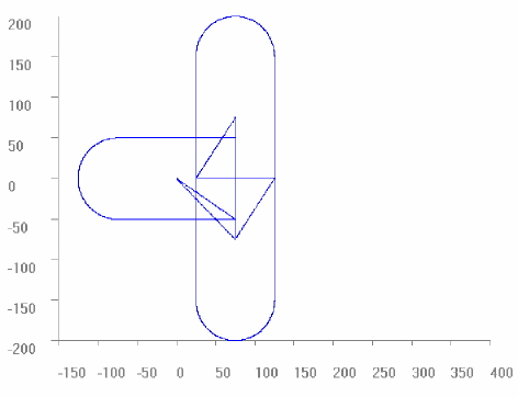
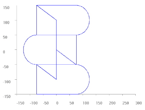
Programing Example

Rotation in a plane (contour rotation)
%L part
N10 G0 G90 X0 Y0
N30 G1 F5000 Y50
N40 X75
N50 G2 Y-50 R50
N60 G1 X0
N70 Y0
N80 M29
%ang1.nc
N100 G53 G17
N110 LL part
N130 #ROTATION ON [ANGLE -45 CENTER1=10 CENTER2=100]
N140 LL part
N150 G21 (mirroring of X coordinates)
N160 LL part
N170 G18 (warning expected)
N190
M30
Same contour as in the previous program but within #CS of -15°.
%L part
N10 G0 G90 X0 Y0
N30 G1 F5000 Y50
N40 X75
N50 G2 Y-50 R50
N60 G1 X0
N70 Y0
N80 M29
% ang1cs.nc
N99 #CS ON[0,0,0,0,0,-15]
N100 G53 G17
N110 LL part
N130 #ROTATION ON [ANGLE -45 CENTER1 10 CENTER2 100]
N140 LL part
N150 G21 (mirroring of X coordinates)
N160 LL part
N190 #CS OFF
M30
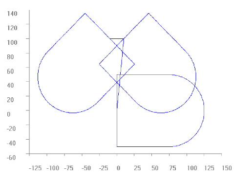
%L Trajectory0
N10 G54 G90 X0 Y0
N20 G0 X75 Y-50
N30 Y50
N40 X-75
N50 G3 X-75 Y-50 R50
N60 G0 X75
N70 X0 Y0
N80 M29
%ang2.nc
F1000
N100 LL Trajectory0
N200 G92 G90 Y-25
N400 #ROTATION ON [ANGLE 90 CENTER1 75 CENTER2=-50]
N600 LL Trajectory0
N700 G92 G90 Y25
N900 #ROTATION ON [ANGLE=-90 CENTER1 75 CENTER2 50]
N60 LL Trajectory0
N70 M30
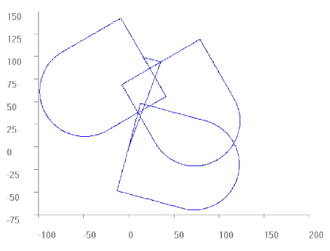
%L Trajectory0
N10 G54 G90 X0 Y0
N20 G1 X75 Y-50
N30 Y50
N40 X-75
N50 G3 X-75 Y-50 R50
N60 G1 X75
N70 X0 Y0
N80 M29
%ang3.nc
N10 F4000 G90
N15 #ROTATION ON
N20 LL Trajectory0
N30 G90 G92 Y100
N35 #ROTATION ON [ANGLE 180]
N40 LL Trajectory0
N50 G90 G92 Y-100
N55 #ROTATION ON [ANGLE 180]
N60 LL Trajectory0
N70 M30
%L UPRG1
N1 X0 Y0 Z0
N10 X25
N30 X0
N40 Y25
N50 Y0
N60 X10
N70 Y10
N80 X0 Y0
N90 Y10
N100 X10 Y0
N110 G03 I-5 J5 Y10
N120 G1 X0 Y0
M17
%L UPRG2
N2 X0 Y0 Z0
N10 X25
N20 G02 I0.8
N30 G1 X0
N40 Y25
N45 G02 J0.8
N50 G1 Y0
N120 G1 X0 Y0
M17
%L UPRG3
N3 G1 X0 Y0 Z0
N10 X4 Y4
N20 G02 I1 J1
N30 G1 X0 Y0 Z0
M17
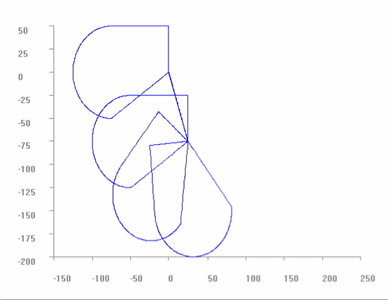
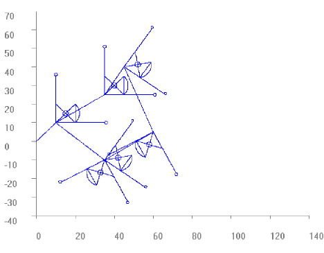
%ang4.nc
N1 G1 X0 Y0 Z0 F1000
N500 G92 X10 Y10
N510 LL UPRG1
N520 #ROTATION ON [ANGLE 0 CENTER1 25 CENTER2 15]
N540 LL UPRG1
N550 G92 X20 Y25
N560 #ROTATION ON [ANGLE –35]
N570 LL UPRG1
N580 G92 X35 Y-10
N590 #ROTATION ON [ANGLE=V.G.ROT_ANGLE-117]
N600 LL UPRG1
N610 #ROTATION ON [CENTER1 0 CENTER2 0]
N620 LL UPRG1
N630 #ROTATION ON [ANGLE=V.G.ROT_ANGLE+117]
N640 LL UPRG1
N650 #ROTATION ON [ANGLE=V.G.ROT_ANGLE+35]
N500 G92 X10 Y10
N510 LL UPRG2
N520 #ROTATION ON [ANGLE 0 CENTER1 25 CENTER2 15]
N540 LL UPRG2
N550 G92 X20 Y25
N560 #ROTATION ON [ANGLE –35]
N570 LL UPRG2
N580 G92 X35 Y-10
N590 #ROTATION ON [ANGLE=V.G.ROT_ANGLE-117]
N600 LL UPRG2
N610 #ROTATION ON [CENTER1 0 CENTER2 0]
N620 LL UPRG2
N630 #ROTATION ON [ANGLE=V.G.ROT_ANGLE+117]
N640 LL UPRG2
N650 #ROTATION ON [ANGLE=V.G.ROT_ANGLE+35]
N500 G92 X10 Y10
N510 LL UPRG3
N520 #ROTATION ON [ANGLE 0 CENTER1 25 CENTER2 15]
N540 LL UPRG3
N550 G92 X20 Y25
N560 #ROTATION ON [ANGLE –35]
N570 LL UPRG3
N580 G92 X35 Y-10
N590 #ROTATION ON [ANGLE=V.G.ROT_ANGLE-117]
N600 LL UPRG3
N610 #ROTATION ON [CENTER1 0 CENTER2 0]
N620 LL UPRG3
N630 #ROTATION ON [ANGLE=V.G.ROT_ANGLE+117]
N640 LL UPRG3
N650 #ROTATION ON [ANGLE=V.G.ROT_ANGLE+35]
M30
Test of relative and absolute programming:
%L contour_1
N1 G1 G91 (all positions with G91)
N2 X20
N3 Y20
N4 X20
N5 Y20
N6 X20
N7 Y20
N8 X20
N9 Y20
N10 X20
N11 Y20
N12 X5
N13 Y-3
N14 Y3
N15 X-5
N16 G90 X0
N17 Y0
N18 X5
N19 Y-3
N20 Y0
N21 X0
#MSG SYN["contour_1 finished"]
M17
%L contour_2
N100 G1 (same contour, X with G91, Y with G90)
N101 G91 X20
N102 G90 Y10 (transl. offset in Y is 10)
N103 G91 X20
N104 G90 Y30
N105 G91 X20
N106 G90 Y50
N107 G91 X20
N108 G90 Y70
N109 G91 X20
N110 G90 Y90
N111 G91 X8
N112 G91 Y-4
N113 G91 Y4
N114 G91 X-8
N115 G90 X0
N116 Y0
N117 X8
N118 Y-4
N119 Y0
N119 Y0
N120 X0
#MSG SYN["contour_2 finished"]
M17
%L contour_3
N200 G1 (same contour, Y with G91, X with G90)
N201 G90 X0 (transl. offset in X is 20)
N202 G91 Y20
N203 G90 X20
N204 G91 Y20
N205 G90 X40
N206 G91 Y20
N207 G90 X60
N208 G91 Y20
N209 G90 X80
N210 G91 Y20
N211 G91 X11
N212 G91 Y-5
N213 G91 Y5
N214 G91 X-11
N215 G90 X0
N216 Y0
N217 X11
N218 Y-5
N219 Y0
N220 X0
#MSG SYN["contour_3 finished"]
M17
%L contour_4
N300 G1 G90 (same contour with G90)
N301 X0 (transl. offset in X is 20)
N302 Y10 (transl. offset in Y is 10)
N303 X20
N304 Y30
N305 X40
N306 Y50
N307 X60
N308 Y70
N309 X80
N310 Y90
N111 G91 X14
N312 G91 Y-6
N313 G91 Y6
N314 G91 X-14
N315 G90 X0
N316 Y0
N317 X14
N318 Y-6
N319 Y0
N320 X0
#MSG SYN["contour_4 finished"]
M17
%ang5.nc
N5001 G0 G90 X0 Y0 F5000
N501 #ROTATION ON [ANGLE 0 CENTER1 20 CENTER2 10]
(Note: with angle != 0 the contours are
( not congruent because of difference
( of absolute and incremental movement!)
N502 #ROTATION ON
N503 LL contour_1
N504 #ROTATION OFF
N5002 G0 G90 Y0
N5003 X0
N505 #ROTATION ON
N506 LL contour_2
N507 #ROTATION OFF
N5004 G0 G90 Y0
N5005 X0
N508 #ROTATION ON
N509 LL contour_3
N510 #ROTATION OFF
N5006 G0 G90 Y0
N5007 X0
N511 #ROTATION ON
N512 LL contour_4
N513 #ROTATION OFF
N5005 G0 G90 Y0
N5006 X0
N210 M2
After selecting valid rotation angular. The offsets for the rotation point may firstly be considered with the first absolute programming (G90).
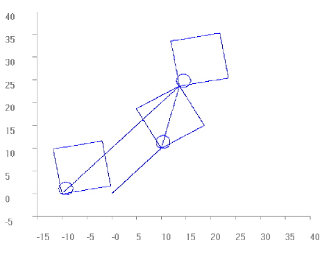
%ang6.nc
N10 G90 X0Y0Z0 G1 F200
N20 #ROTATION ON [ANGLE 30 CENTER1 10 CENTER2 10]
N30 X0 Y0
N40 G3 I1 J1 F500
N50 G01 X10
N60 Y10
N70 G90 X0
N80 G90 Y0
N90 X10 Y10
(New rotation parameters.
(Note: Centre offset has no effect until an absolute (G90) position
(has been programmed. However, the angle is effective.
N100 #ROTATION ON [ANGLE 10 CENTER1 –10 CENTER2 0]
N110 G3 I1 J1 F500
N120 G01 G91 X10
N130 G91 Y10
N140 G91 X-10
N150 G91 Y-10
(Make the new centre effective by first absolute position:
N200 G90 X0 Y0
N210 G3 I1 J1 F500
N220 G01 X10
N230 Y10
N240 X0
N250 Y0
M30
Transforming the absolute or relative programmed circle centre point:
%ang_cent.nc
N10 F2000 G53
N11 G0 X0 Y0 G90
(---------------------------------------------------------------------)
(4 times the same circle with different programming of circle centre point)
(---------------------------------------------------------------------)
N12 G0 X0 Y0 G90
N13 Y50
N14 X-75
N15 G3 X-75 Y-50 G161 I-75 J0 (absolute centre)
N16 G0 X0 Y0 G90
N17 Y50
N18 X-75
N19 G3 X-75 Y-50 G162 I0 J-50 (relative centre)
N20 G0 X0 Y0 G90
N28 #ROTATION ON [ANGLE 0 CENTER1 25 CENTER2 –75]
(---------------------------------------------------------------------)
(The same with LIN and ANG offset active (ED=0))
(---------------------------------------------------------------------)
N80 G0 X0 Y0 G90
N90 Y50
N100 X-75
N110 G3 X-75 Y-50 G161 I-75 J0 (absolute centre)
N120 G0 X0 Y0 G90
N130 Y50
N140 X-75
N150 G3 X-75 Y-50 G162 I0 J-50 (relative centre)
N360 G0 X0 Y0 G90
(---------------------------------------------------------------------)
(The same rotated by 50° (unnecessary I / J omitted) )
(---------------------------------------------------------------------)
N370 #ROTATION ON [ANGLE 50]
N380 G0 X0 Y0 G90
N390 Y50
N400 X-75
N410 G3 X-75 Y-50 G161 I-75 (J0) (absolute centre, not prog. is 0)
N420 G0 X0 Y0 G90
N630 Y50
N640 X-75
N650 G3 X-75 Y-50 G162 I0 J-50 (relative centre)
N655 G0 X0 Y0 G90
(---------------------------------------------------------------------)
(The same rotated by 95° )
(---------------------------------------------------------------------)
N660 #ROTATION ON [ANGLE 95]
N670 G0 X0 Y0 G90
N680 Y50
N690 X-75
N700 G3 X-75 Y-50 G161 I-75 J0 (absolute centre)
N710 G0 X0 Y0 G90
N730 Y50
N740 X-75
N750 G3 X-75 Y-50 G162 I0 J-50 (relative centre)
N760 G0 X0 Y0 G90
M30