Mirroring in the plane (G21/G22/G23/G20)
The term "virtual coordinates" is used to mirror in the plane. When mirroring is executed, the virtual coordinates (xm) are the values entered in the NC program. By contrast, the real coordinates (xr) are mirrored and are executed in reality. Mirror functions always act on the first and second main axes of the current plane (G17, G18, G19). The third main axis of the current plane is not mirrored.
The following mirroring functions are available (illustrated example for G17, X-Y plane): | ||
G21 | Mirroring programmed paths on the X axis | modal |
| xm = -xr |
|
| ym = yr |
|
G22 | Mirroring programmed paths on the Y axis | modal |
| xm = -xr |
|
| ym = yr |
|
G23 | Superimpose G21 and G22 | modal |
| xm = -xr |
|
| ym = yr |
|
G20 | Deselect the mirroring function | modal, initial state |
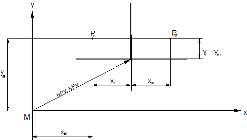
xm , ym | Virtual coordinates |
xr , yr | Mirrored coordinates |
xa , ya | Absolute coordinates |
Contours to be mirrored should be specified in a subroutine. This subroutine is then called after the mirroring function. Mirroring is modal.
Notice

If mirroring is programmed when tool radius compensation is selected, the side of the compensation also changes. This means that, when G41 is active, the equidistance to the programmed path after mirroring is calculated on the right of the contour (G42: TRC right of contour). This also happens even if the path direction is changed.
Tool offsets and shifts (e.g. G54, G92, #PSET...) are not mirrored with G21, G22 and G23.
By contrast, the reference point offset (G92) is mirrored with the mirror function G351.
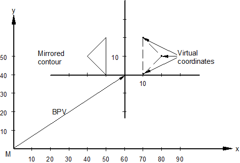
Programing Example

Mirroring in the plane (G21)
%L DREIECK (Subroutine)
N10 G90 X10 Y20 (Define the mental)
N20 G91 X10 Y-10 (Coordinates to be mirrored)
N30 X-10 Y-10
Y20
N50 M29
%SPIEGELUNG (Main program)
N10 G92 G90 X60 Y40 (Reference point offset)
N20 G01 F500 (Straight line at feed 500)
N30 G21 (Mirroring in the X axis)
N40 LL DREIECK (Call subroutine)
N60 G92 G90 X0 Y0 (Reset the reference point offset)
N70 M30
Attention

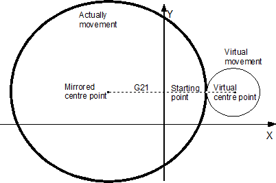
Note the following when circles are mirrored:
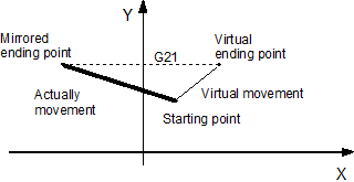
In general, only coordinates set in the NC program are mirrored (i.e. only the centre point coordinates for a full circle). After selecting the mirroring function, the motion path runs directly to the target point. The starting point of the motion path is not mirrored.
Consequence: In the motion block only the target point is mirrored but not the complete motion path (see Fig.: * Mirroring the target point in motion block”)
Effect: If a full circle is programmed as a motion block and the starting/target points are not in 0/0, a new circle radius results from mirroring the centre point coordinates and the contour is changed (see Fig.: "Changing the contour when mirroring a full circle”).
Effect:
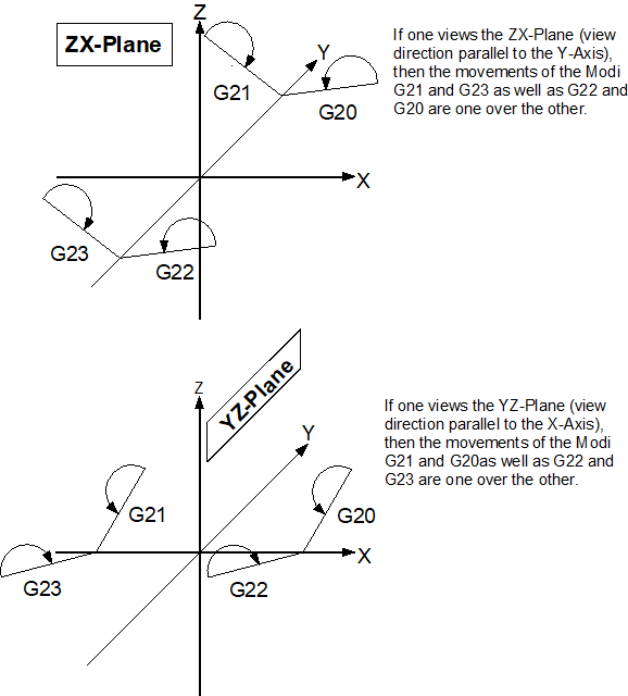
3D considerations:
If the mirroring functions are selected in a different plane than the XY plane (G18, G19), note that the direction of rotation for circular interpolation may change depending on the selected plane: In addition, mirroring has no impact on the Z coordinate, i.e. the virtual and mirrored values in the Z direction are always identical.