Contour line programming (#ANG)
In technical drawings, simple contours (e.g. turned parts) are often described by specifying angles and individual positions. This measurement is quick and easy to enter into an NC program using contour line programming.
Contour lines are located in a plane (G17, G18, G19) and describe a different type of linear block programming in the form of straight lines.
Contour line programming with active circular interpolation will result in an error message output.
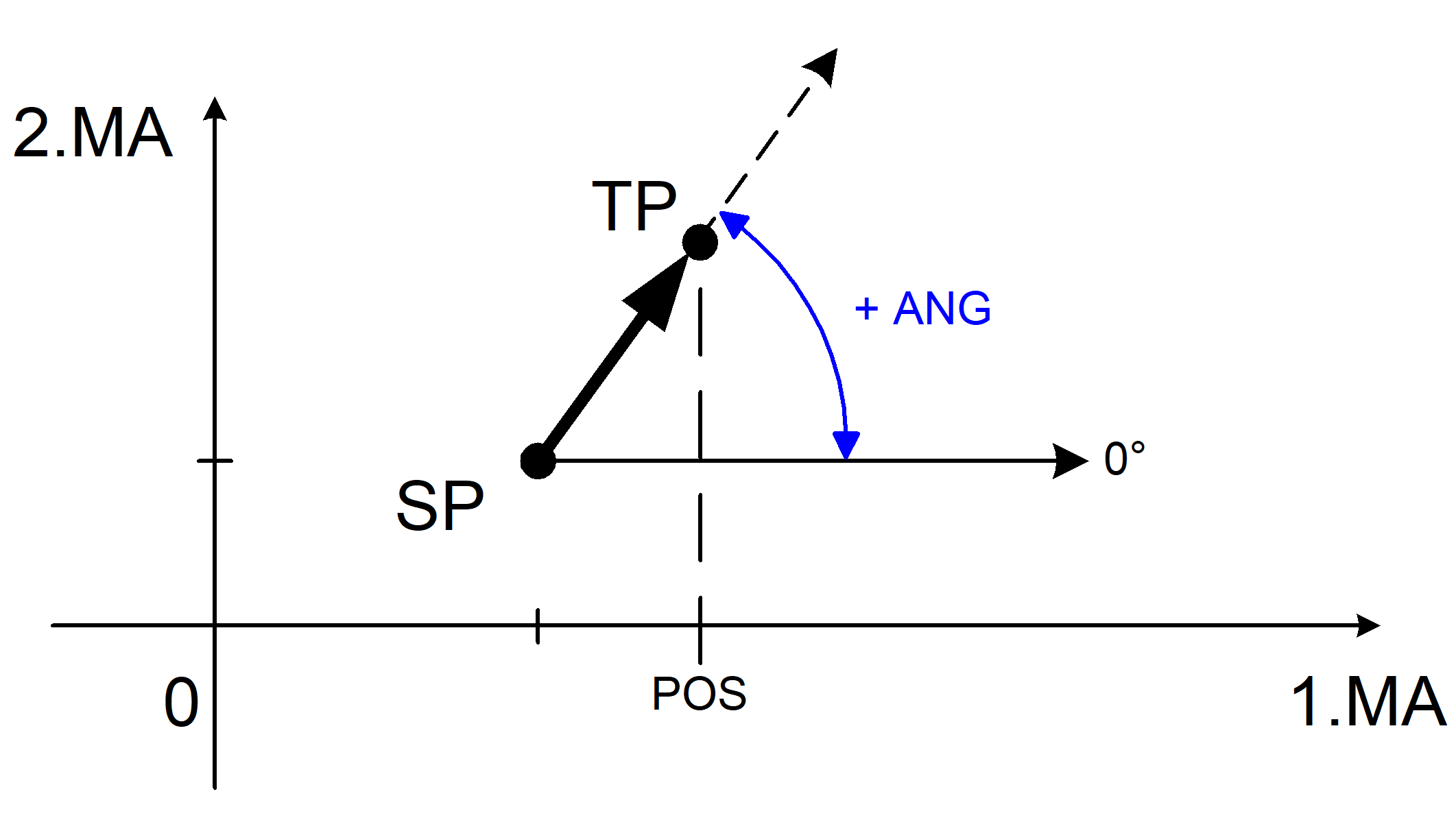
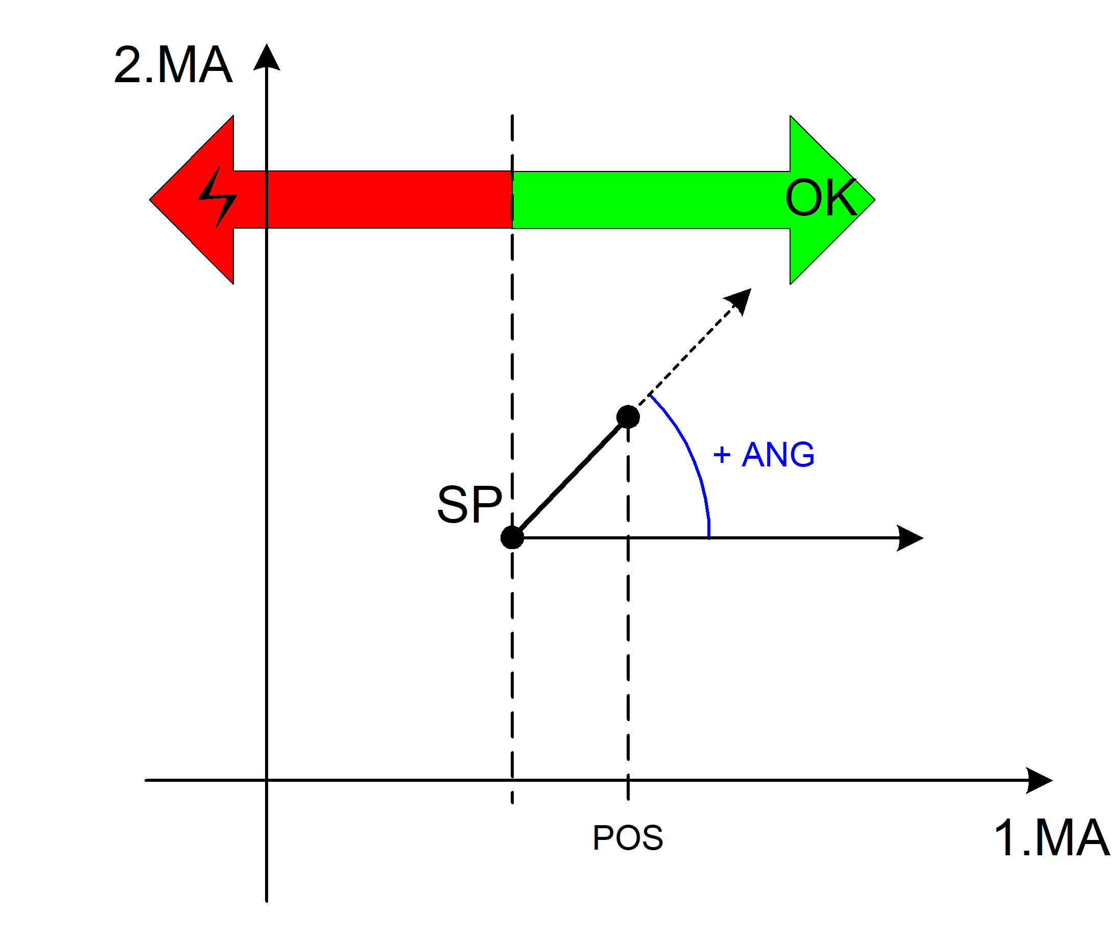
Contour line consisting of a straight line
Starting with a starting point (SP), a contour line describes the linear block by:
- Specifying an angle (ANG)
- and a coordinate (POS) of the target point (ZP).
The controller calculates the unknown second target point coordinate from the angle and the programmed coordinate. It is irrelevant which of the two target point coordinates is specified. Normally, this depends on the measurement in the actual drawing.
Syntax example for G17 plane: | |
#ANG=.. X.. | Y.. | modal |
#ANG=.. | Angle relative to the first main axis of the active plane in [°] |
X.. | Coordinate of target point in the first main axis in [mm, inch] |
Y.. | Coordinate of target point in the second main axis in [mm, inch] |
Contour line with coordinate in the first main axis
Programing Example

Contour line in G17 with target coordinate in X
N10 G17 G90 G0 X10 Y10 ;Approach start position
N20 G01 F2000 #ANG=60 X20 ;Contour line to target point: X20, Y27.3205
N30 ...
Contour line with coordinate in the second main axis
Programing Example
Contour line in G17 with target coordinate in Y
N10 G17 G90 G0 X10 Y10 ;Approach start position
N20 G01 F2000 #ANG=35 Y20 ;Contour line to target point: X24.2812, Y20
N30 ...
Page break
Validity check of target point:
When the complete target point is determined, a check is made whether the programmed target point coordinate (POS) can be reached with the specified angle. If the target point cannot be reached with the specified angle, an error message is output.
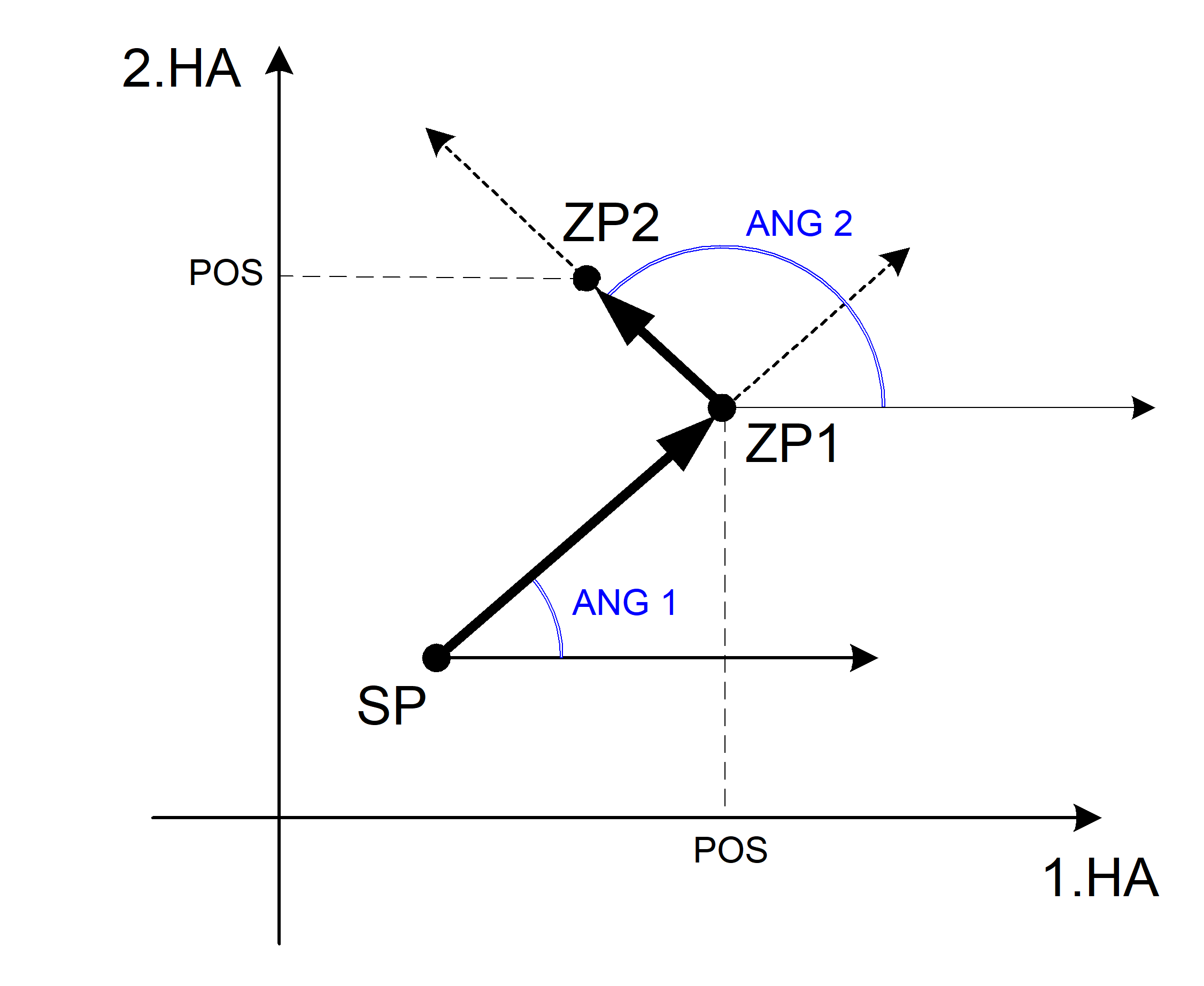
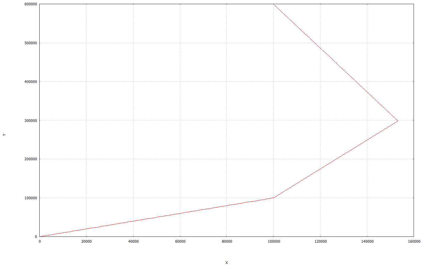
Contour line consisting of 2 straight lines
A contour line consisting of 2 straight lines can be programmed in various combinations of angles and target coordinates. The associated rules are explained in the permitted cases listed below.
Page break
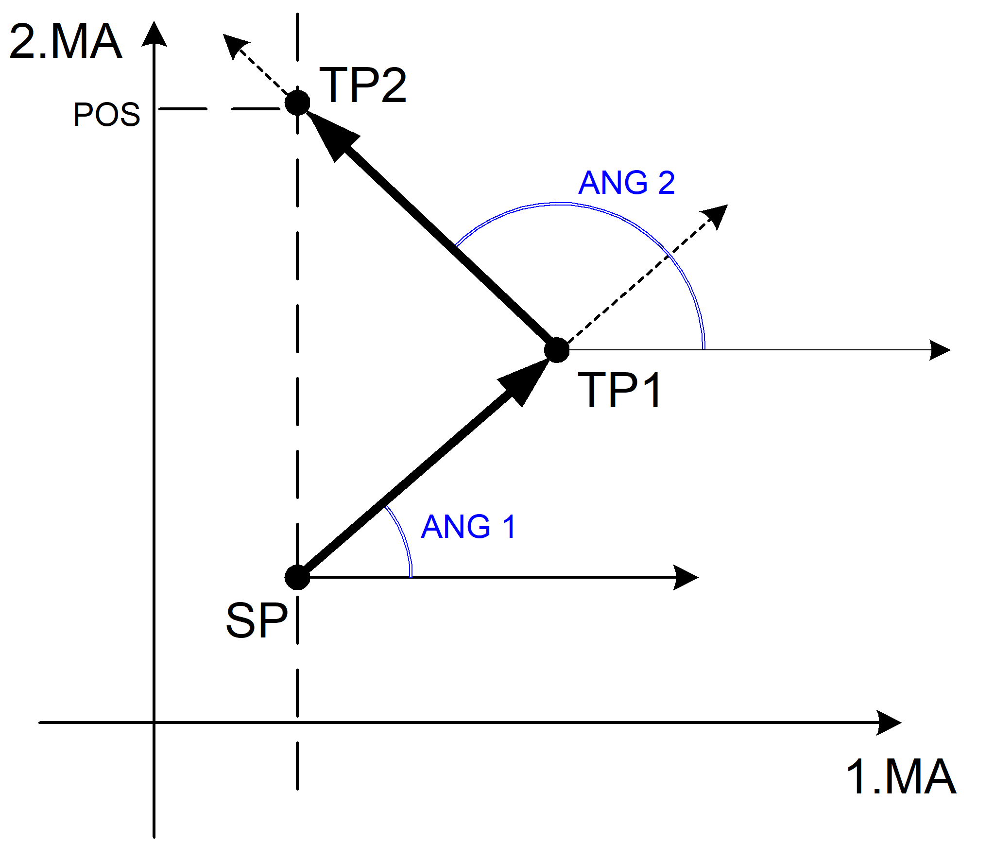
Case 1: Combination of two angles and two target coordinates
The target point ZP1 of the first straight line results from an angle ANG1 and a target coordinate. Based on this, the target point ZP2 of the second straight line also results from an angle ANG2 and a target coordinate. The target coordinates of ZP1 and ZP2 can be programmed as absolute (G90) or relative (G91).
Programing Example
Contour line with 2 straight lines in G17 and 2 angles with target coordinates
N10 G17 G90 G0 X10 Y10 ;Approach start position
N20 G01 F2000 #ANG=25 X30 ;Straight line 1, target point: X30, Y19.3258
N30 #ANG=120 Y50 ;Straight line 2, target point: X12.2904, Y50
N40 ...
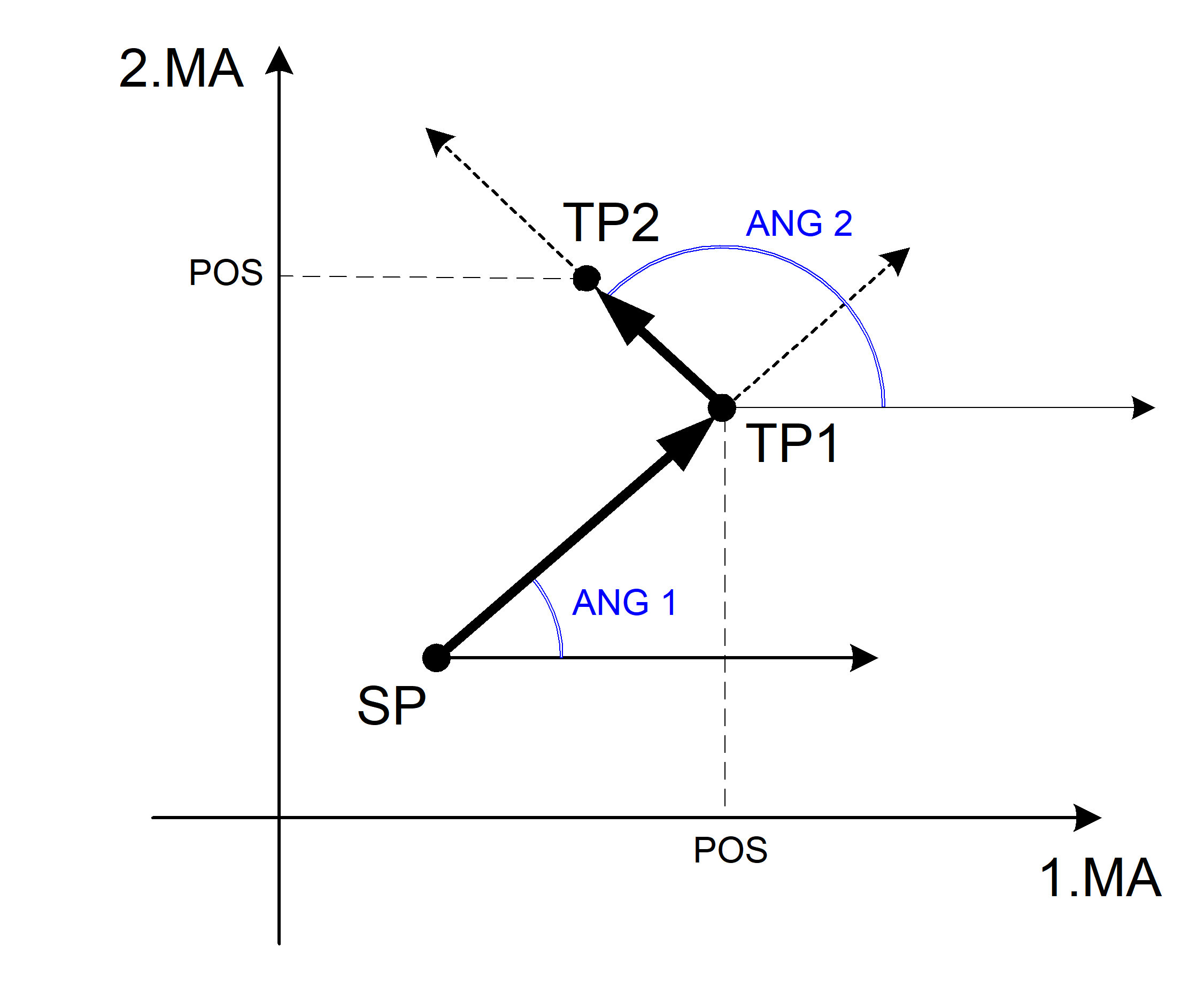
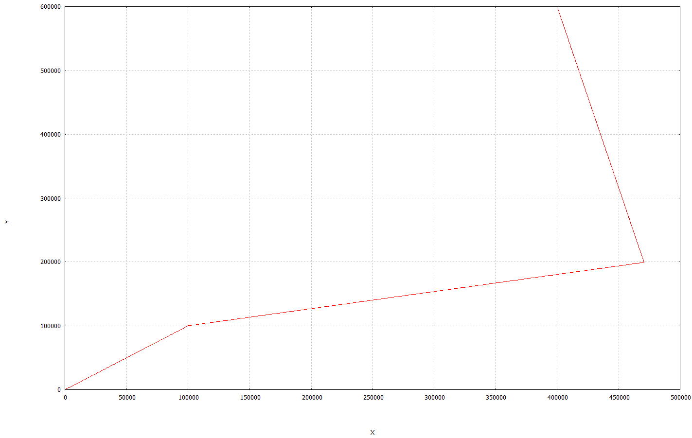
Case 2: Combination of two angles and target coordinate 2
The angles ANG1 and ANG2 are each programmed completely (Cartesian) for the two straight lines and for the second straight line of the target point ZP2. The target point ZP2 must always be specified as absolute (G90). The target point of the first straight line ZP1 can then be determined as the intersecting point of the straight lines.
Programing Example
Contour line with 2 straight lines in G17 and 2 angles and complete target point 2
N10 G17 G90 G0 X10 Y10 ;Approach start position
N20 G01 F2000 #ANG=15 ;Straight line 1
N30 #ANG=100 Y60 ;Straight line 2, target point 2
N40 ...
Special case 2-1: Combination of two angles and one target coordinate 2
The angles ANG1 and ANG2 are each programmed for the two straight lines and only one target coordinate of ZP2 for the second straight line. The other coordinate of target point ZP2 results from the associated components of starting point SP. The target coordinate ZP2 must always be specified as absolute (G90). The target point of the first straight line ZP1 can then be determined as the intersecting point of the straight lines.
Programing Example
Contour line with 2 straight lines in G17, 2 angles and incomplete target point 2
N10 G17 G90 G0 X10 Y10 ;Approach start position
N20 G01 F2000 #ANG=75 ;Straight line 1
N30 #ANG=100 Y60 ;Straight line 2, one target coordinate
N40 ...
Special case 2-2: Combination of two angles, no target coordinates
If only angles and no target coordinates are programmed, the target points ZP1 and ZP2 are identical to the starting point SP. Only two motions are then possible perpendicular to the current plane.
Validity check of target points:
This checks whether the programmed target points can be reached with the programmed angle starting from the starting point. The orientations resulting from the programmed angles define the valid range for the target points.
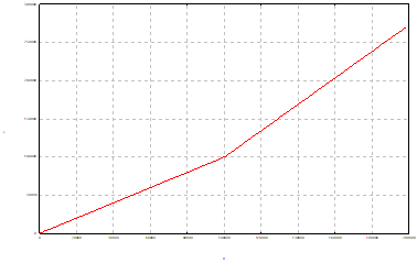
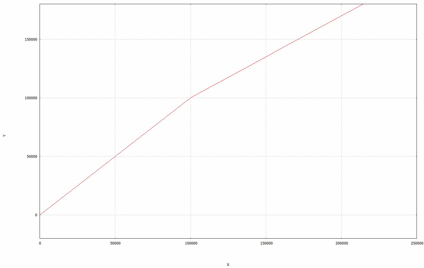
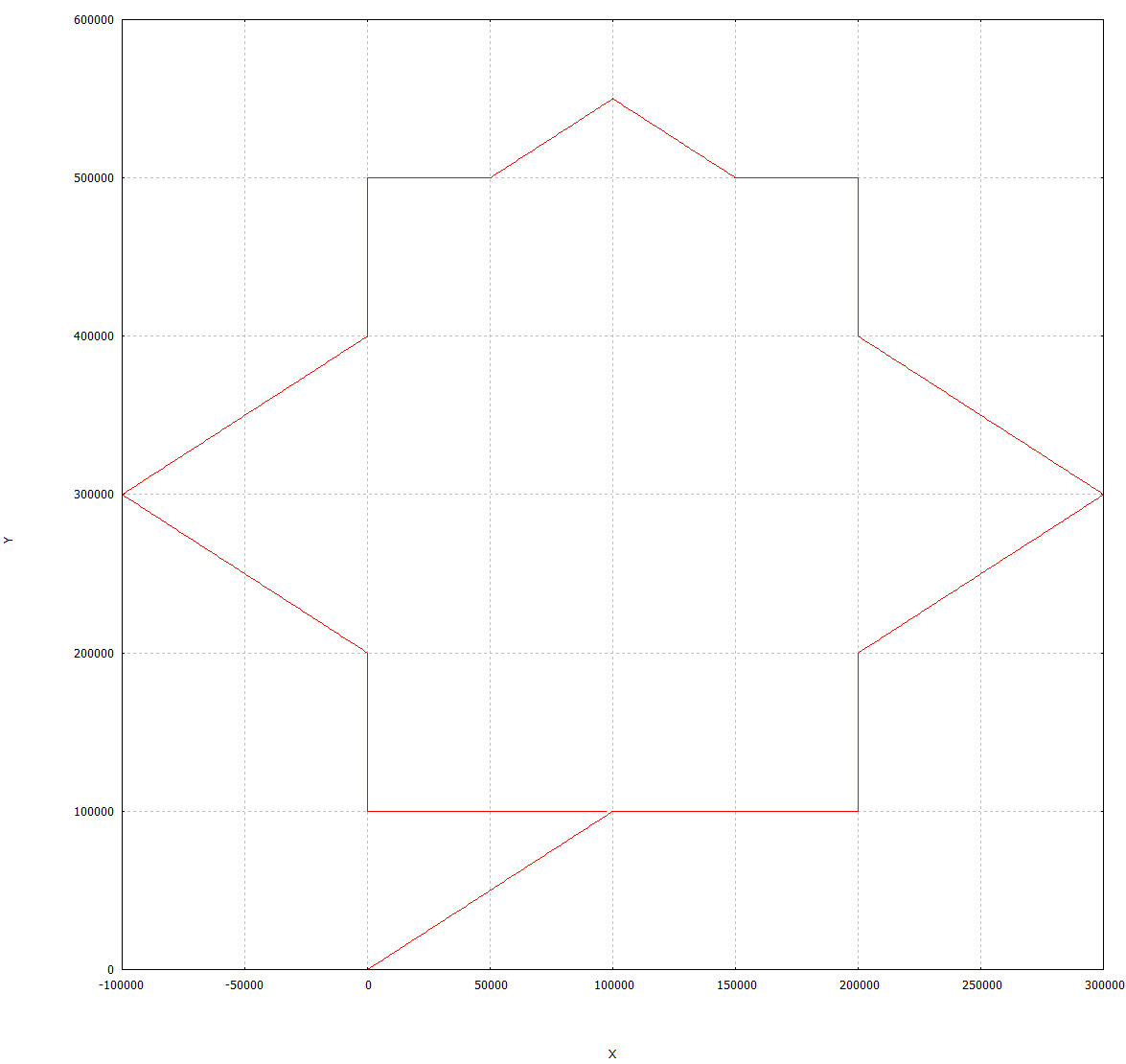
Contour line consisting of several straight lines
Any number of straight lines can be connected together to describe a contour. The target points of the straight lines must then be clearly determinable geometrically. The programming rules for a contour line with 2 straight lines must also be complied with for linked contours.
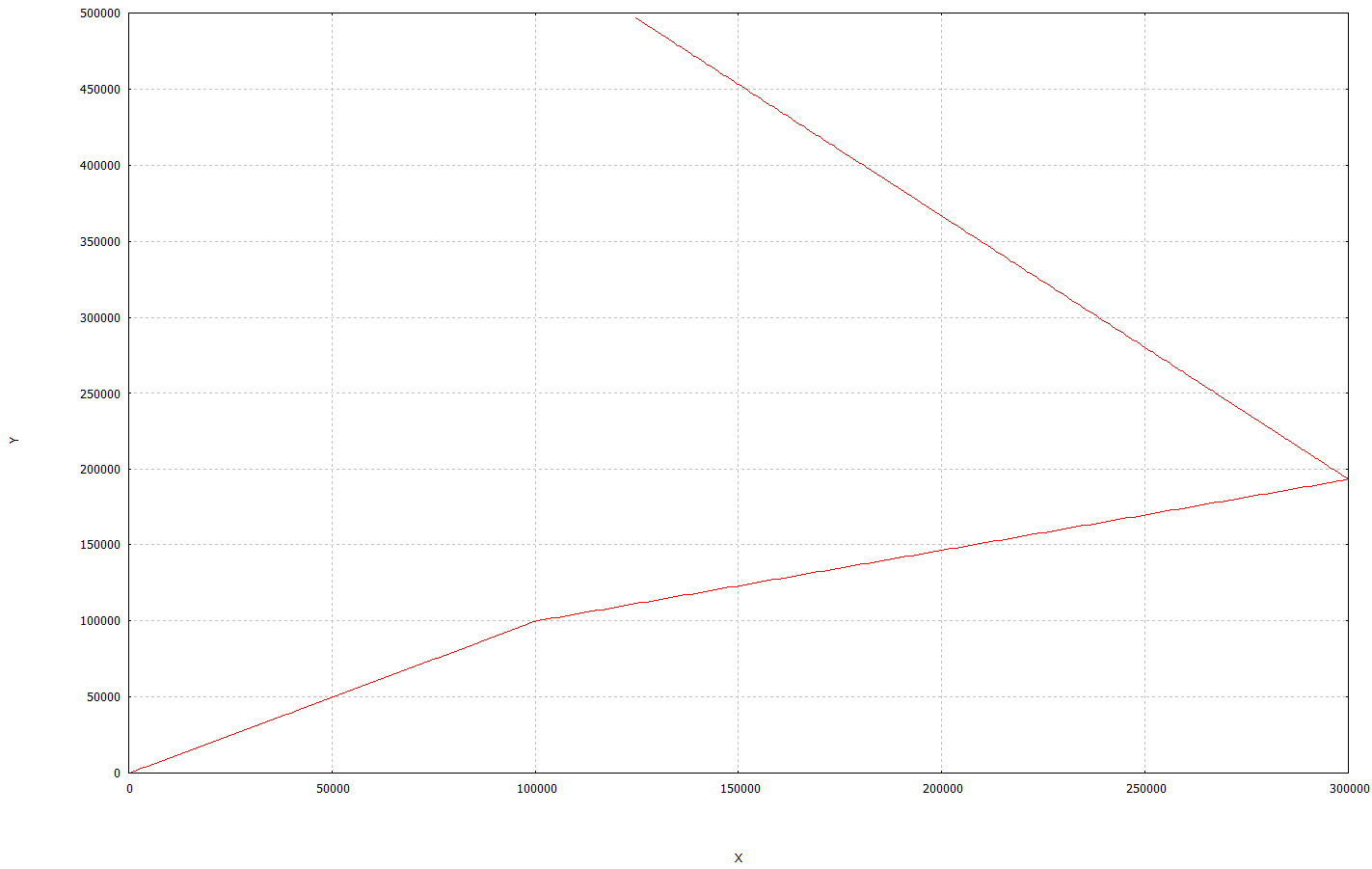
Programing Example
Contour line with several straight lines in G17
N020 G17 G90 G01 F2000
N030 X10 Y10 ; Move to start position
N040 #ANG=0 X20
N050 #ANG=90 Y20
N060 #ANG=45 X30
N070 #ANG=135 X20
N080 #ANG=90 Y50
N090 #ANG=180 X15
N100 #ANG=135 Y55
N110 #ANG=225 Y50
N120 #ANG=180 X0
N130 #ANG=270 Y40
N140 #ANG=225 Y30
N150 #ANG=315 Y20
N160 #ANG=270 Y10
N170 #ANG=0 X10
N180 M30
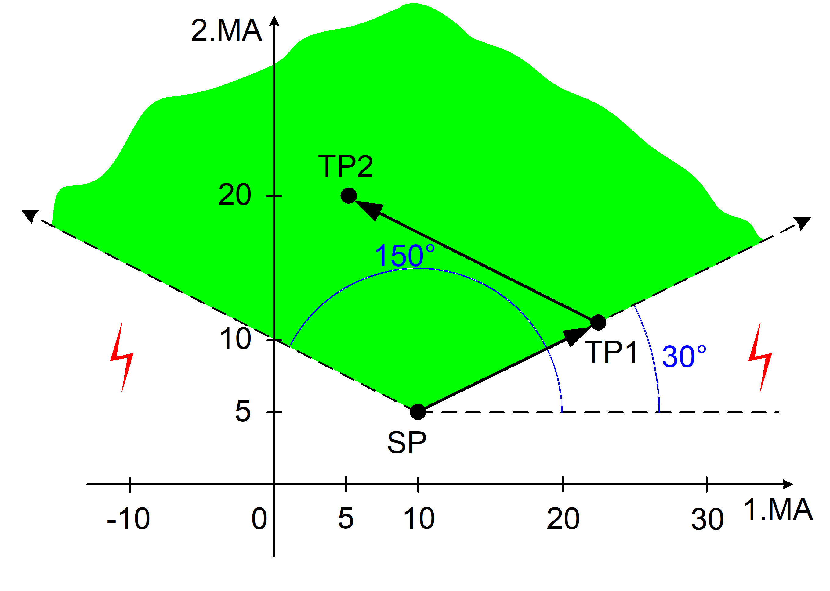
Contour lines in combination with chamfers and roundings
Contour lines can be combined with a complete scope of functions for programming chamfers and roundings (see section Chamfers and roundings). This is illustrated by the programming example for a turned part below.
Programing Example
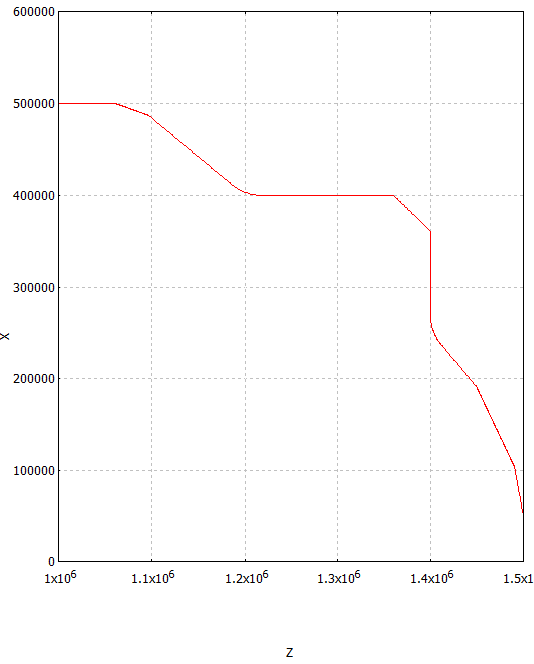
Contour line of a turned part with chamfers and roundings
N030 G18 G90 G00 X0 Z150
N040 X5 G01 F2000
N050 #ANG=100 #CHR=5 #FRC=1000
N060 #ANG=130 X25 Z140 #RND=5 #FRC=1500
N070 #ANG=90 X40 #CHR=4 #FRC=1000
N080 Z120 #RND=5 #FRC=1500
N090 #ANG=140 X50 #CHR=2 #FRC=1000
N100 Z100
N110 ...