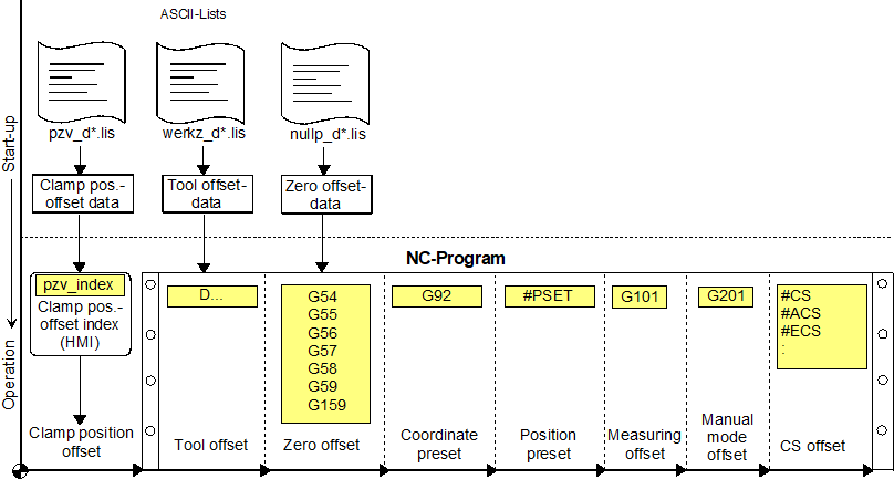
Coordinate systems
After the homing, the controller is at the machine zero point or in the machine coordinate system. If this is followed by inputs from the NC program (e.g. X100), the programmed coordinates (Index p) then coincide with the absolute coordinates (Index a):
| xa = xp ya = yp |
|
Offsets occur due to the definition of workpiece coordinate systems. The spatial positions in the workpiece coordinate system differ from the coordinate systems that are defined by the physical machine axes. Here a distinction must be made between programmed, constant, translatory offsets in a single axis and dynamic offsets that result from kinematic (e.g. cylindrical ⇔ Cartesian) or geometric transformations (e.g. tool radius compensation, mirroring), which in general affect several axes.
For example, the zero point can be offset from machine zero point M to a freely selectable workpiece zero point W or a workpiece coordinate system by a zero offset (NPV-G54…G59). The absolute coordinates result from adding NPV and programmed coordinates:
| xa = xNPV + xp ya = yNPV + yp |
|
Irrespective of these NPVs specified by the zero offset data block, additional offset types can be explicitly programmed in the subroutine, e.g. with G92 X... Y ... Z ...
This reference point offset (BPV) is added to the preceding NPV. The absolute coordinates can then be determined as follows:
| xa = xNPV + xBPV + xp ya = yNPV + yBPV + yp |
|
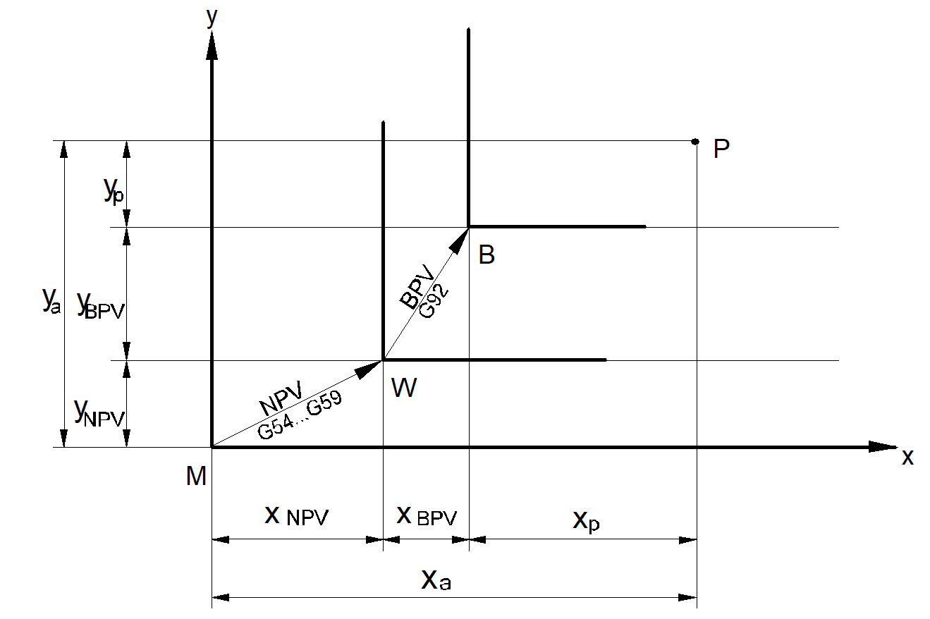
| xa, ya : | Absolute coordinates |
| xp, yp : | Programmed coordinates |
| xNPV, yNPV : | Zero offset |
| xBPV, yBPV : | Reference point offset |
| M : | Machine zero point |
| W : | Workpiece zero point |
| B : | Reference point for coordinates |
| P : | position |
The coordinate display on the user interface shows active offsets by the remaining difference between the coordinates of physical machine axes (ACS) and workpiece coordinates (PCS). However, some offsets also result from manipulating machine and workpiece coordinates (e.g. tool radius compensation, mirroring) and therefore do not result in a coordinate difference.
The tables below provide an overview of the additional offset types in anticipation of the sections further below. The following conditions for the parameters are active:
Activation and deactivation infer the time when the offset becomes visible on the user interface as a coordinate difference or change in coordinates. However in general, an offset only becomes physically active at the earliest with the first motion that follows any activation or deactivation. For example, deactivation at program end leads to a compensating motion in the first motion of the following program.
Programmable offsets (linear, constant)
No. | Description | Definition | ACS – PCS | Activation | Deactivation | Temporary |
1 | Reference point offset | NC program | yes | NC block | NC block “G92 X0 Y0“ or | "#SUPPRESS "#MCS ON" |
2 | Zero offset | List | yes | NC block “G54...G59” | NC block “G53“ | “#SUPPRESS "#MCS ON" |
3 | Clamp position offset | list | yes | Program paths | NC program start | “#SUPPRESS "#MCS ON" |
4 | Tool | List | yes | NC block “D..“ | NC block “D0“ | “#SUPPRESS "#MCS ON" |
5 | Position preset | NC program | yes | NC block "#PSET.." | NC block | “#SUPPRESS "#MCS ON" |
6 | CS | NC program | yes | NC block | NC block “#CS OFF“ | "#MCS ON" |
7 | ACS offset | NC program | yes | NC block | NC block | "#MCS ON" |
Offsets caused by geometric transformation (linear, dynamic):
No. | Description | Definition | ACS – PCS | Activation | Deactivation | Temporary |
8 | CS | NC program | yes | NC block | NC block “#CS OFF“ | "#MCS ON" |
9 | ACS | NC program | yes | NC block | NC block “#ACS OFF“ | "#MCS ON" |
10 | Contour rotation | NC program | No | NC block | NC block | "#MCS ON" |
11 | Mirroring | NC program | No | NC motion block | NC motion block | Not |
12 | Tool radius compensation | NC program | No | NC block G41/42 | NC block G40 | Not |
13 | Kinematic | NC program | No | NC block | NC block | "#MCS ON" |
Offsets caused by special functions:
No. | Description | Definition | ACS – PCS | Activation | Deactivation | Temporary |
14 | Offset | Handwheel | yes | NC block "G201" | NC block "G202" | Not |
15 | Offset | NC program | yes | NC block "G101" | NC block "G102" | "#SUPPRESS OFFSETS" "#MCS ON" |
16 | Offset | NC program | No | NC block | Not possible | Not |
The NC command #SUPPRESS OFFSETS only acts within an NC block
The NC command #MCS ON deactivates any offsets until command #MCS OFF is programmed.
Within every (A)CS the offset types 1, 2 and 5 are stored "locally”.