Realisation of the FBs
The PLCopen FBs internally map the state diagram below
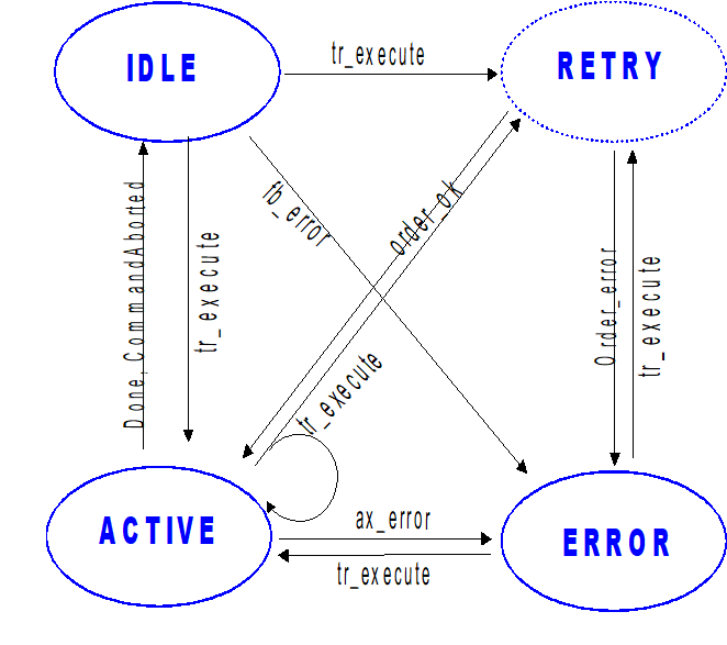
The state machine in IEC 61131-3 Structured Text displayed below shows the framework for implementing the commands in an FB: The individual actions are written in the pseudo code.
(*==========================================================*)
(* State distributor for commanding the HLI
(*==========================================================*)
CASE fb_state OF
(*==========================================================*)
(*==========================================================*)
FB_IDLE,
FB_ERROR:(* *)
IF ( tr_execute.Q = TRUE OR retry ) THEN
(* checking of the FB's input parameters *)
(* check whether transition is allowed *)
(* try to send the MC order. *)
(* IF (sendorder = OK) THEN fb_state := FB_ACTIVE; END_IF *)
END_IF
(*==========================================================*)
(*==========================================================*)
ACTIVE:(* *)
IF ( tr_execute.Q = TRUE OR retry) THEN
(* check whether FB's ax_ref connection has changed since idle state*)
(* checking of the FB's input parameters *)
(* check whether transition is allowed *)
(* try to send the MC order. *)
END_IF
(* collection of Acknowledge *)
(* IF (Acknowledge = OK) THEN fb_state := FB_IDLE; END_IF *)
(*==========================================================*)
(*==========================================================*)
ELSE
(*// default: Impermissible state *)
END_CASE;
The FBs are not aware of any reset transition and, instead, after a preceding FB_ERROR that follows retriggering of the FBs, an attempt is simply made to assert the new command issued. This is why the state distributor does not differentiate between FB_IDLE and FB_ERROR with respect to HLI commands issued.
The FB_RETRY state does not appear as an explicit state in the state distributor, but is kept in a variable in the states FB_IDLE,FB_ERROR and FB_ACTIVE in case the FB in the corresponding state cannot assert commands issued at first go.
The unique command number is kept as a global PLC data item and incremented by the FBs only at the time after successful commands issued from the FB_IDLE and FB_ERROR states, and is noted in its instance data.
When a command is issued out of the FB_ACTIVE state, a new command with the same command number is sent to the MC and an internal counter in the FB, which counts how many commands pertaining to one command number, is incremented.
This method dispenses with complex administration of the command numbers that have been issued and the associated acknowledgements received.
When an FB is triggered, it checks whether the state transition that would be triggered by execution of the FB in the FBSD is permitted at all in the momentary state of the FBSD ("transition allowed"). If this is not the case, the command is not sent at all and, instead, the FB reports a command issuing error (= error at FB level). In such a case, the axis state never changes because no command at all has been sent. See the next section for more details.