MC_MoveCircAbs
This function block commands a circular interpolated motion of the axes of an axis group by specifying absolute target positions.
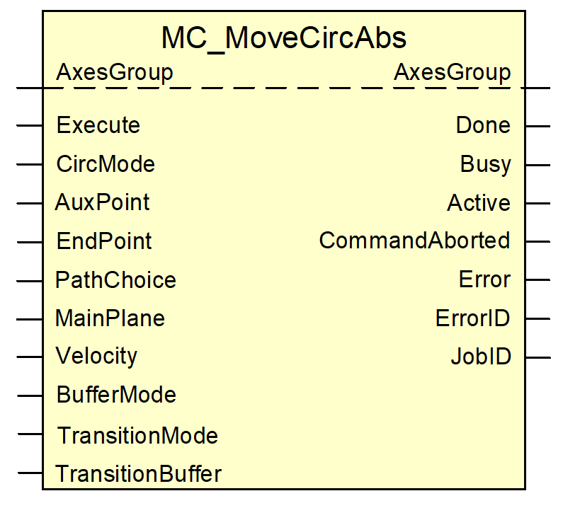
Block diagram
FB parameters
VAR_IN_OUT | ||
Variable name | Data type | Description |
AxesGroup | AXES_GROUP_REF | Axis group reference |
VAR_INPUT | ||
Variable name | Data type | Description |
Execute | BOOL | The circular interpolated motion of the axes starts on a rising edge depending on the positions specified as absolute coordinates. |
CircMode | MC_CIRC_MODE | This input defines the meaning of the values at the “AuxPoint” and “PathChoice” inputs. The permitted values for this input are: mcCenter = 1 mcRadius = 2 and the are described in more retail in Meaning of the “CircMode“ input with absolute programming. |
AuxPoint | ARRAY [0..HLI_CH_AX_MAXIDX] OF LREAL | Absolute coordinates of a point in the current coordinate system. The type of additional point is defined by the value at the “CircMode“ input. Default unit [0.1 µm] |
EndPoint | ARRAY [0..HLI_CH_AX_MAXIDX] OF LREAL | Absolute coordinates of the end point of a circular motion in the current coordinate system. Default unit [0.1 µm] |
PathChoice | MC_CIRC_PATHCHOICE | Determines whether the motion is travelled from the start point to the end point in a clockwise or counter clockwise direction on the circular path defined by the values of “CircMode”, “AuxPoint” and “EndPoint”. The permitted values for this input are described in the Meaning of the “PathChoice“ input input. |
MainPlane | MCV_MAIN_PLANE | The value of this input defines the main plane of the programming coordinate system where the circle is interpolated. The permitted values for this input are: mcvMpXY = 0 mcvMpZX = 1 mcvMpYZ = 2 |
Velocity | LREAL | Maximum path velocity of the motion. This value need not be reached. Default unit [10-3 °/ s] |
BufferMode | MC_BUFFER_MODE | The input defines when a job is activated provided that other jobs are already active when the FB is commanded or are waiting for execution. It also defines the path generated at the transition between 2 jobs. The following values are possible: mcAborting = 0 mcBuffered = 1 mcBlendingPrev = 3 |
TransitionMode | UDINT | 0: TMNone (no transition motion is inserted, default setting) 2: TMConstantVelocity 3: TMCornerDistance 4: TMMaxCornerDeviation 10: TMConstDeviation 11: TMIntermediatePoint 12: TMDynamicOptimized |
TransitionParameter | MCV_ARRAY_TRANS_PARAM | See Section Path blending and transition modes |
VAR_OUTPUT | ||
Variable name | Data type | Description |
Done | BOOL | TRUE indicates that the axes have reached their end position. |
Busy | BOOL | TRUE indicates that the function block is executing a job. |
Active | BOOL | TRUE indicates that the function block sent the job to the MC. |
CommandAborted | BOOL | TRUE indicates that the currently active command sent by the FB was aborted by another job. |
Error | BOOL | TRUE indicates that an error occurred. |
ErrorID | WORD | Error code |
JobID | UDINT | Ordinal number of the last job sent by the FB. |
Notice

If, due to the values specified at the “AuxPoint“ and “EndPoint“ inputs, a distance results in the direction of the 3rd main axis of the orthogonal coordinate system in the plane of the circular path, the application of this FB leads to a helical motion (see [PROG//Helikalinterpolation]).