Overview of transition conditions on contouring (blending and transition modes)
If more than one motion FB is executed, the traversed path and the velocity profile will depend on the blending and transition modes transferred to the FBs.
The table below provides an overview of the permitted transitions:
BufferMode | TransitionMode | Description |
mcAborting |
| Aborts the current active motion command and starts a separate motion command. |
mcBuffered |
| The motion command only becomes active when all the previously commanded motions have been executed. When the job is completed, the velocity of the axis group is 0. As a result there is no blending to the next motion job and therefore the “TransitionMode” input is not evaluated. |
mcBlending | TMNone | No contouring curve is inserted between 2 commands of the motion FB. The transition velocity between 2 commands depends on whether the command of the 2nd FB changes the motion direction. |
TMConstantVelocity | A contouring curve is inserted in all these cases. An FB with one of these values at the “TransitionMode” input is not executed immediately since the following NC block is required to calculate the contouring curve. With the last FB in a chained sequence of FBs, Buffered value must be applied to the “BufferMode” input. | |
TMCornerDistance | ||
TMMaxCornerDeviation | ||
TMConstDeviation | ||
TMIntermediatePoint | ||
TMDynamicOptimized |
The following definitions for contouring curves are contained in the PLCopen specification:
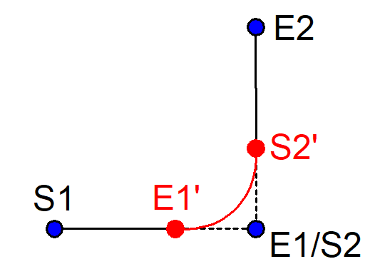
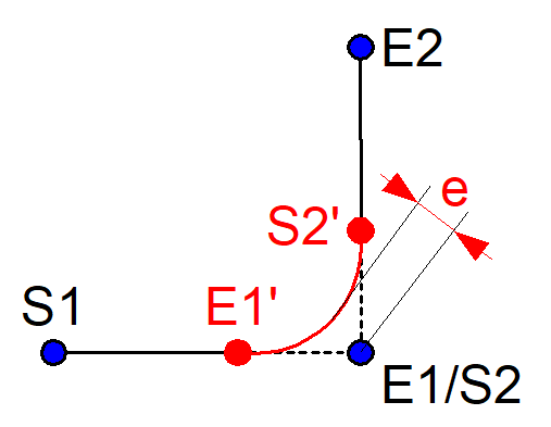
Contouring curve: | Inserted curve which modifies the original programmed path (E1’ - S2’). |
Pre-block | Motion block before the contouring curve (S1 – E1) |
Post-block | Motion block after the contouring curve (S2 – E2) |
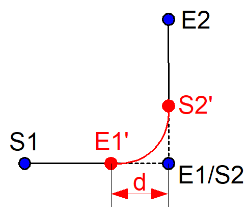
Corner distance | Distance (d) from the start point of the contouring curve (E1’) to the programmed target point (E1), see figure below. |
Corner deviation | The shortest distance between the programmed corner point (E1/S2) and the contouring curve, see figure below. |