Cam description by interpolation point tables
In the ISG-MCE, interpolation point tables and tables with alternating LINE/POLY5 motion sections are supported as cams.
The entries (= lines in the cam table) in the interpolation point tables are represented by equidistant interpolation points of the slave axis across the modulo range of the master axis. This is why no master positions are kept in this table type. When processing the cams, the modulo range of the master axis is split into sections of equal size in “number of interpolation points”. The interpolation point entries for the slave axis are represented by metric positions of the salve axis within the associated position intervals of the master axis.
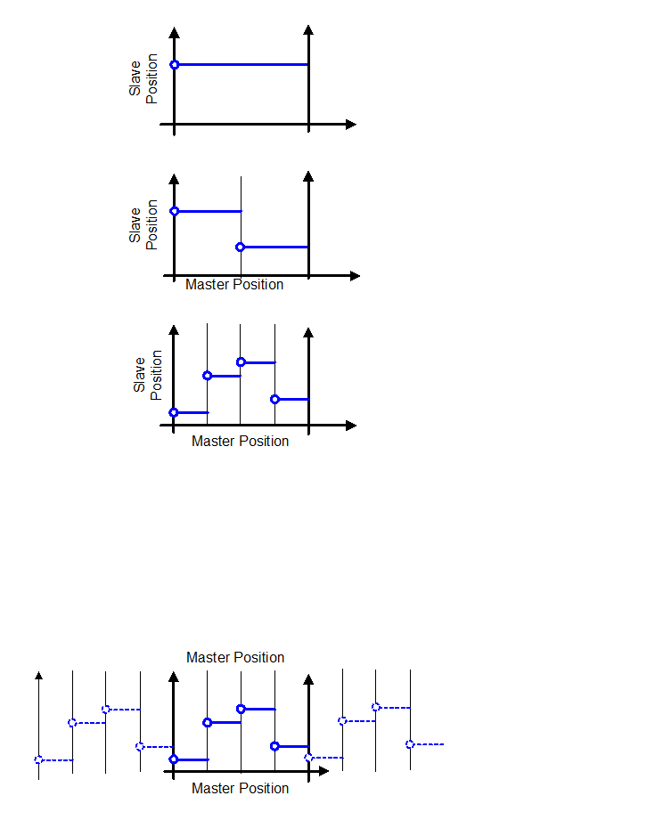
This form of cam description is only suitable for use with closed scanning because, according to the definition, the slave position at the end of the cam is implicitly assumed as being equal to the slave position at the start of the cam.
The first table above with precisely one slave position entry is therefore the simplest conceivable cam description in the form of a table. During processing, the slave would move to the entered slave position during the synchronisation phase (ramp-in) and would stay there. The interpolation of equidistant interpolation point tables is described in Sections Online interpolation of interpolation point tables and Closed processing for an endlessly rotating slave axis.
Table entries need not be equidistant in tables containing LINE/POLY5 motion sections. For this reason, the first column always specifies the master position and the second column always specifies the slave position which defines the end of the motion section. The metric unit for master and slave positions is 1E-4° or 1E-4 mm. The Section Processing tables with LINE/POLY5 motion segments describes the interpolation of tables with LINE/POLY5 motion sections.