Definition of coordinate systems
Allowance must be made for various coordinate systems owing to the structure of a machine and its machining programs. The totality of a machine is represented by the reference coordinate system in world coordinates. In turn, the individual axes themselves define coordinate systems, the workpiece and the tool.
The two different coordinate systems mainly used are described below.
Axis coordinate system acs
Each axis has its own coordinate system. Each axis is mounted either on the machine base or on another axis. This means that the machine base or the corresponding axis forms the basis. The axis coordinate system of an axis is fixed with respect to the mounting point of this axis.
Part program coordinate system pcs
This coordinate system is used in the Geometry Description with the DIN 66025 programming language. The data in a part program constitutes program coordinates. Exceptions are G functions which refer to direct axis coordinates.
Other coordinate system designations are listed for the purpose of completeness.
Machine coordinate system mcs
The machine coordinate system represents an abstract coordinate system. It is not bound to a fixed point of the machine. All other coordinate systems refer to this coordinate system.
Workpiece coordinate system wcs
This coordinate system is fixed to a fixed point of the workpiece. The workpiece description by coordinate information refers to this system.
Tool coordinate system tcs
The tool coordinate system has its origin at the clamping point of the tool. Tool information (geometry) refers to this system. Length compensation is therefore specified in tool coordinates. On Cartesian machines, the Z axis may coincide with length compensation.
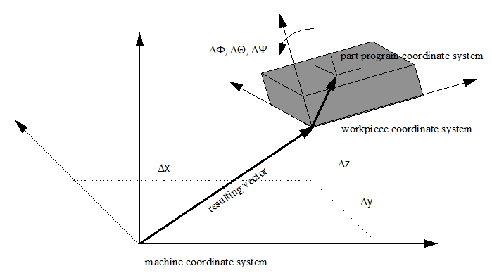
Consequently, data or variables described below always refer to a specific coordinate system. Three coordinate systems are shown in the figure above. The offsets depicted Δx, Δy and Δz and the orientations ΔΦ, ΔΘ and ΔΨ represent the transformation parameters from mcs to wcs. The orientation angles are Euler angles.
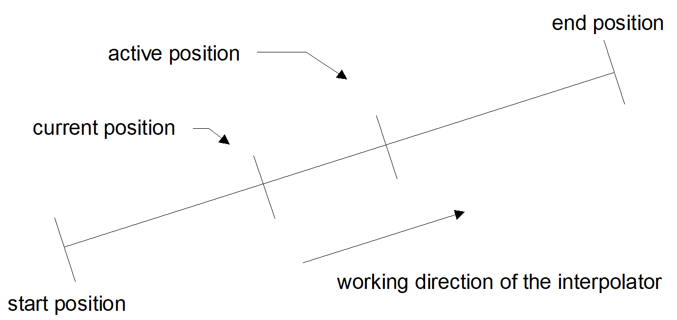
Naming must be supplemented by means of an additional suffix in order to allow for the time aspect. The figure below shows the machining direction of a machining block. The end position represents the programmed value; the active position is the current value of the interpolator; and the current position is the actual position including the control error.