Settings for edge machining (edge_machining.*)
Release Note
This functionality is available as of Release V2.11.2009.12. It is enabled in the start-up list ([STUP]) for each CNC channel as follows (as an example):configuration.channel[<i>].path_preparation.function FCT_DEFAULT | FCT_EMF
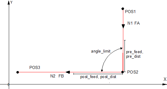
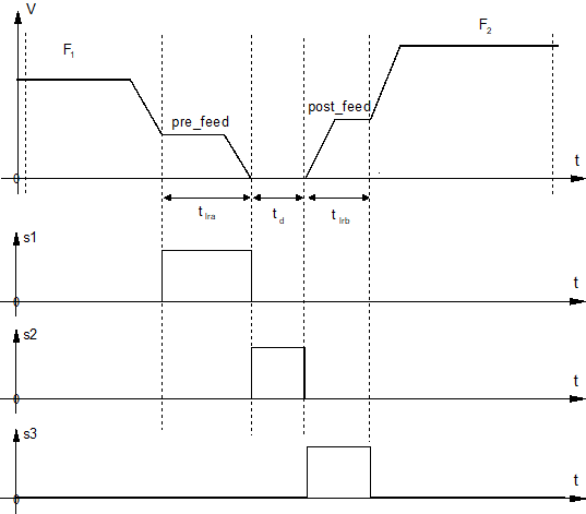
Depending on the machining technology it may be necessary to control the machining process especially on sharp contours (edges). In the case of a sharp edge (defined by the angle difference between two contour elements), the path velocity at the edge is modified depending on pre-defined parameters. In addition, three signals are generated, derived from path velocity. These signals are supplied to the PLC interface (see HLI documentation, Status information of a channel -> Edge functions -> Signal_1, Signal_2, Signal_3). Linear or circular blocks can be programmed as contour elements. No check is made here whether they are inner or outer contours. If the functions ‘Insert chamfers and roundings (G301/G302)’ or tool radius compensation (G41/G42) are active, additional contour elements can be generated. They then result in a different bend angle than exists between the two original contour elements.
The following parameters are required to set the edge machining function:
# Parameterise edge machining function
# ======================================
edge_machining.enable 1
edge_machining.angle_limit 150000 [0.0001°(degrees)]
edge_machining.pre_dist 100000 [0.1µm]
edge_machining.pre_feed 16666 [µm /sec]
edge_machining.wait_time 10000 [[1 µs]]
edge_machining.post_dist 200000 [0.1µm]
edge_machining.post_feed 333333 [µm/sec]
edge_machining.disable_feed_adaption 0
edge_machining.mode 0
#
Additional information
- Enable / disable (P-CHAN-00220)
- Critical bend angle (P-CHAN-00221)
- Distance before the edge (P-CHAN-00222)
- Feed before edge (P-CHAN-00223)
- Waiting time in edge (P-CHAN-00224)
- Distance after the edge (P-CHAN-00225)
- Feed rate after the edge (P-CHAN-00226)
- Switching feed rate adjustment (P-CHAN-00300)
- Edge detection mode (P-CHAN-00301)